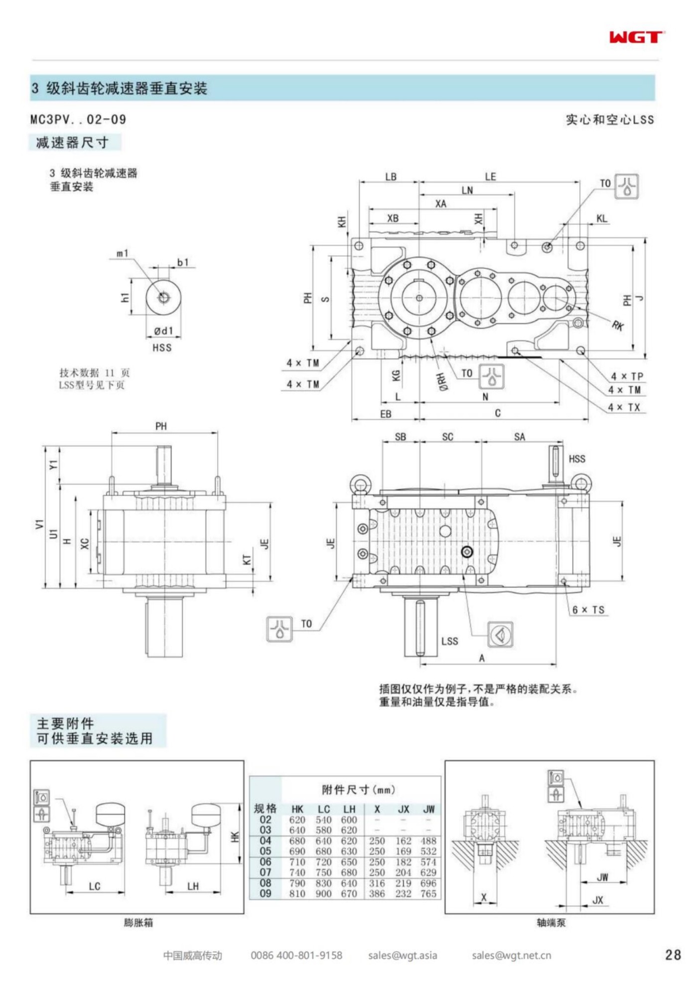
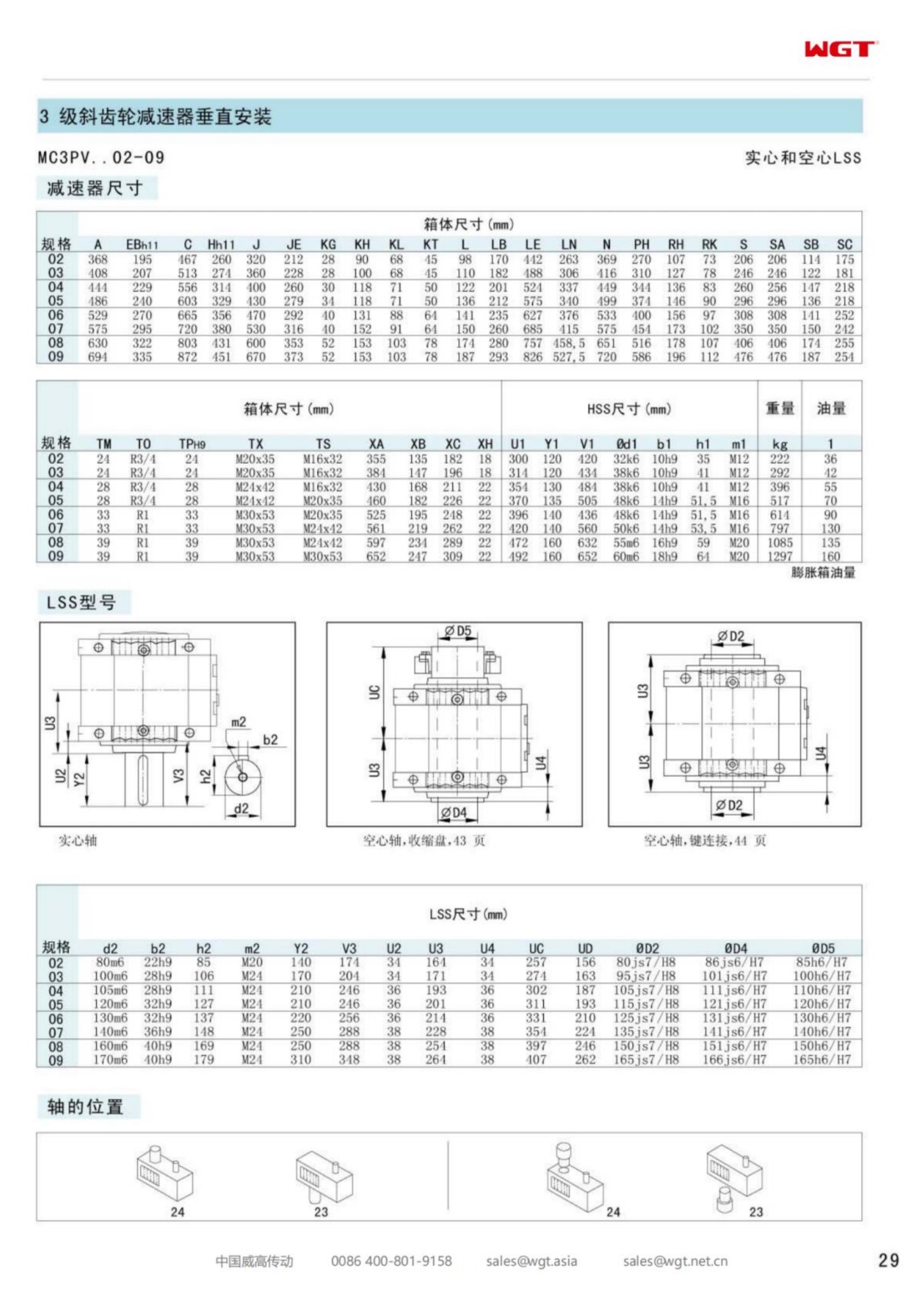
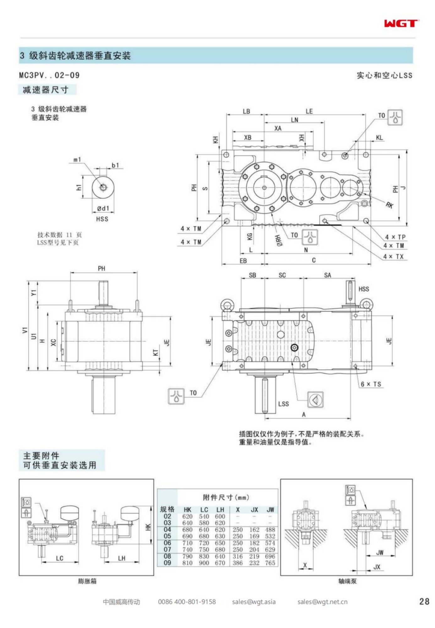
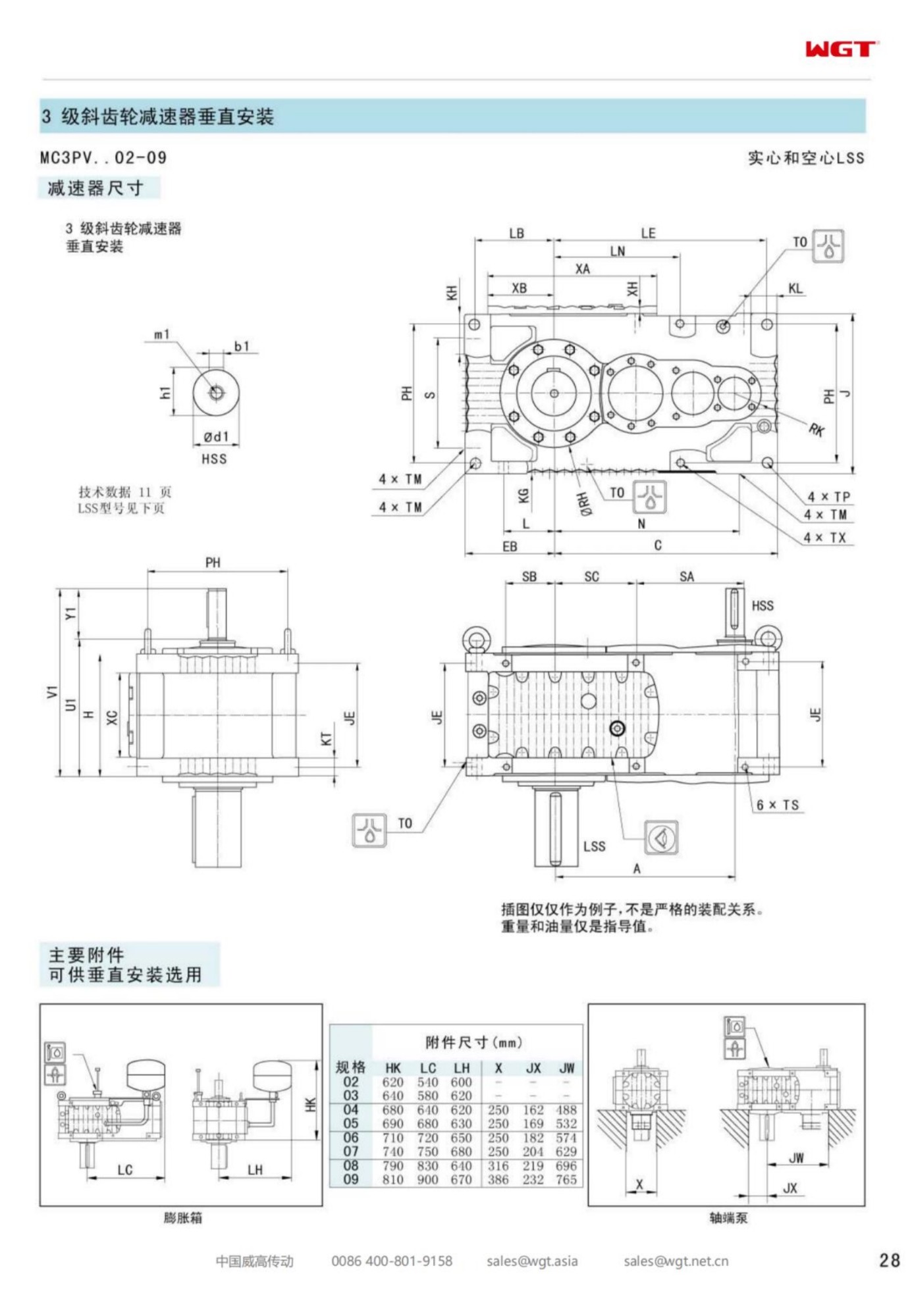
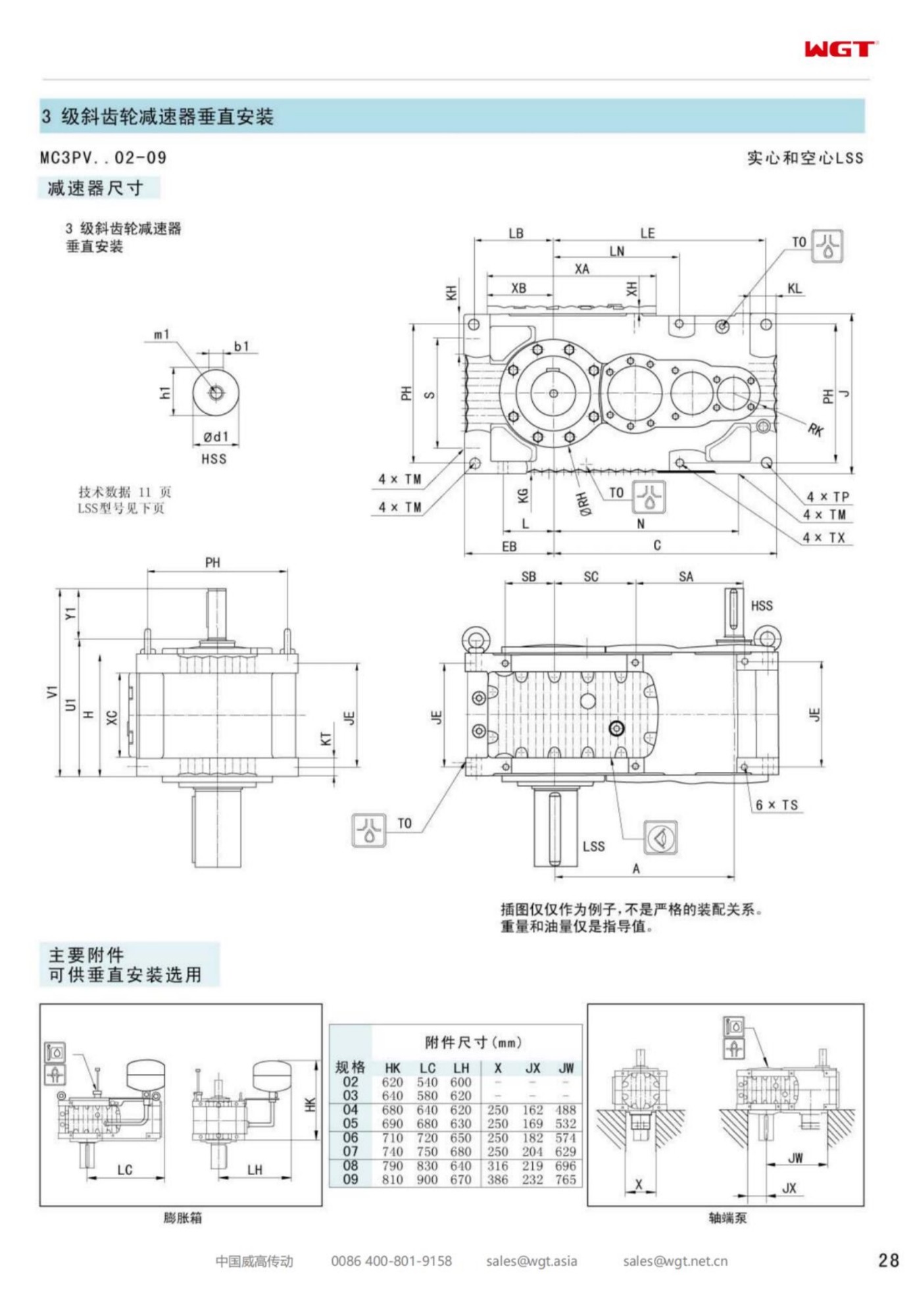
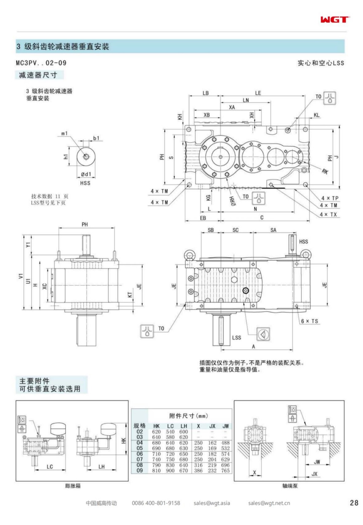
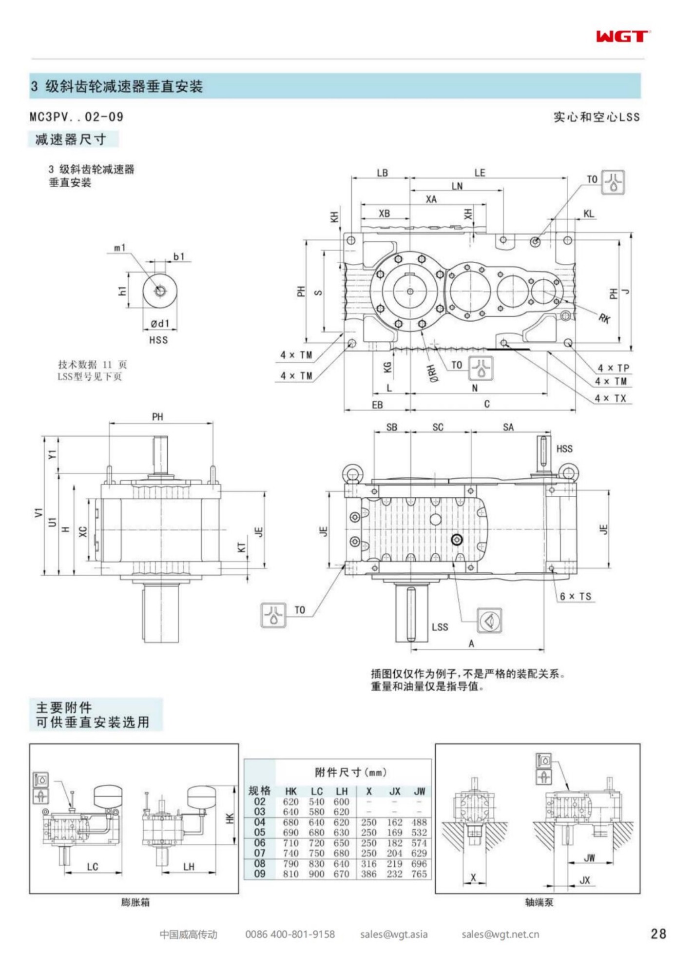
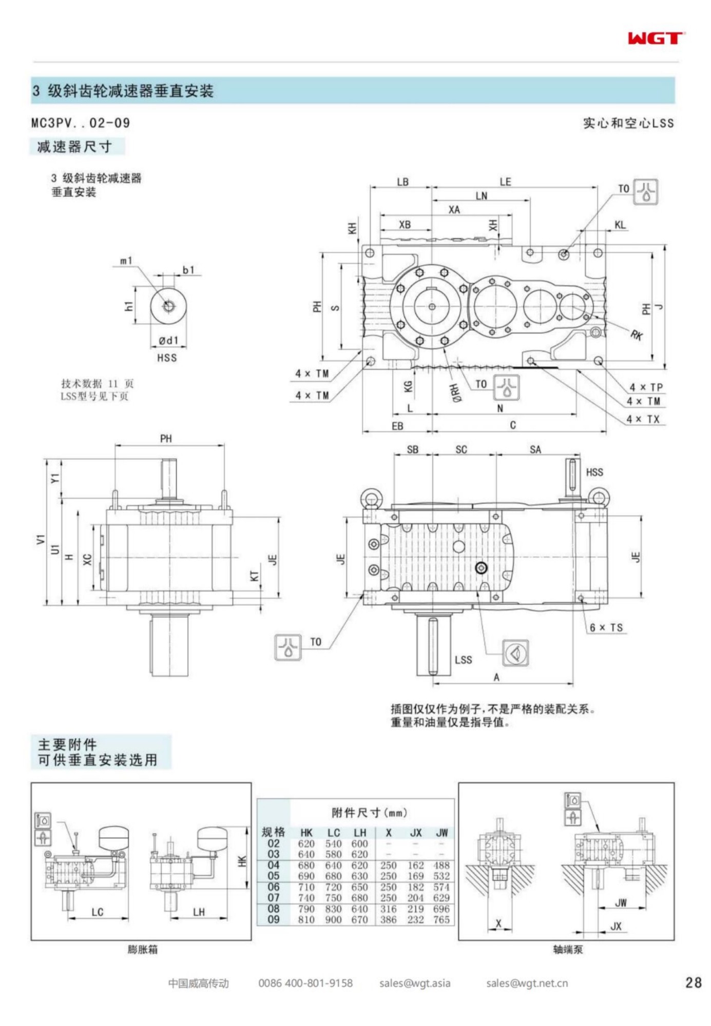
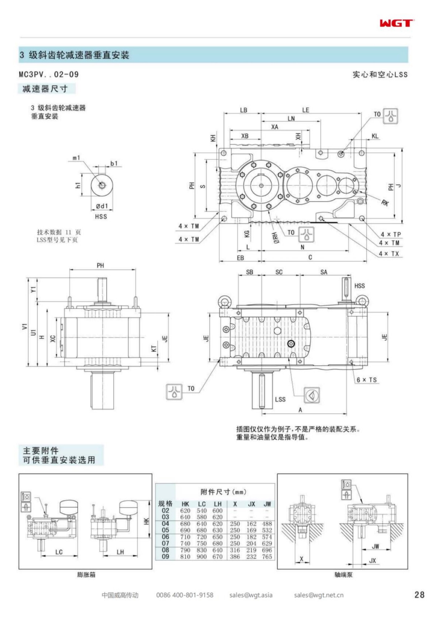
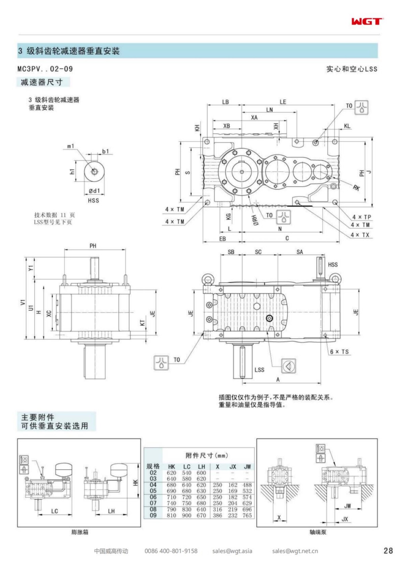
Starch has to be cooked before it can be turned into anything useful, and the cooking happens in a tank where slurry meets steam and an enzyme at a temperature chosen to within a degree or two. The MC3PVST03 vertical solid shaft gear unit turns the agitator in that tank: three helical stages in an upright case, a solid keyed output coupled to the agitator shaft, and a torque arm taking the reaction into the tank structure.
The notes below follow the drive through a liquefaction batch: the change in the slurry, the heat from below, the hygiene the plant has to keep, and the data worth sending with an enquiry.
A Slurry That Changes Character as It Heats
Cold starch slurry is a thin suspension of granules that settles if left alone. Heat it and the granules take up water, swell, and the mixture turns from something that pours into something that resists the paddle.
That change is the whole difficulty of the duty. A drive selected on the cold viscosity is selected on the easiest moment of the batch and will spend the rest of its life working at the hardest.
Decoding MC3PVST03
Six characters, each settling one part of the installation.
| MC | Industrial gear unit family built for continuous plant duty |
| 3 | Three helical reductions inside one upright case |
| P | Parallel-shaft layout, input and output on parallel axes |
| V | Vertical build, output axis pointing down into the tank |
| S | Solid output shaft, keyed and coupled to the agitator |
| T | Torque-arm reaction, no baseplate and no floor drilling |
In a sentence: three-stage industrial unit, parallel shafts, vertical, solid output, torque-arm reaction, third frame of the band.
Mounting on a Liquefaction Tank
Liquefaction tanks are usually stainless, usually insulated, and usually crowded with a steam lance, a temperature probe, a level instrument and a recirculation line. The agitator has to enter through that crowd without fouling any of it.
A torque-arm mounting leaves the tank top free of a baseplate and lets the drive be positioned between the fittings rather than centred on them. The bracket, not the tank top, absorbs the reaction, and the cover stays the thin sheet it was designed to be.
Heat From the Jacket and the Steam Lance
Steam injected directly into the slurry heats the product quickly and heats everything above it slowly. The case of a vertical drive standing on the tank top lives in an air layer that is warm, wet and rising, and the motor fan pulls that layer straight through the motor.
The oil in the case is cooler than the air on a running batch only because the gears are doing little work. Thermal margin at the top of the case, rather than at the sump, is what to check when the tank runs near boiling.
Solid Output Into a Coupled Agitator
A solid output needs a coupling, and a coupling in a food tank needs to be reachable for inspection without breaking sterility. The usual arrangement is a spacer section between the drive and the shaft seal, with the coupling visible through a removable collar.
That spacer is also the place where a small amount of misalignment is absorbed. A rigid joint between a gearbox output and a fabricated tank shaft transmits every weld distortion the tank acquired during its own construction.
Three Stages Through a Rising Viscosity
The agitator's power draw rises steeply as the slurry thickens, and the drive sees that rise as torque at a speed the plant wants to hold. Three helical stages give the ratio and carry the torque without the sliding losses of a worm mesh.
They also keep the case compact for the duty. On a tank deck with limited headroom under a pipe bridge, a short upright case is easier to install and easier to lift off when the mechanical seal beneath it needs attention.
Hygiene Rules and Paint Choice
Nothing on the drive touches product, and everything above the tank is inspected as though it might. A paint system that flakes is a foreign-body risk in a plant that runs metal detectors on the finished powder.
The practical answer is a finish that adheres properly to a prepared surface, fasteners that do not corrode into stains, and no open pockets where dust and condensate collect. Smooth, drainable and inspectable are the three words the plant's quality team will use.
Oil and Food Contact Risk
The oil in the case is separated from product by a seal and a length of shaft, and the separation is only as good as its maintenance. A leaking output seal over a food tank is a product recall question, not an oil consumption question.
A food-grade lubricant, a seal arrangement that can be inspected without dismantling the drive, and a written interval for renewing it are the three items that make the risk manageable. None of them is expensive; all of them need to be decided before the order.
Shaft Whip and Bearing Life
A long vertical shaft turning slowly in a thick slurry will deflect, and the deflection arrives at the gearbox as a bending moment on the output bearing. The steady bearing in the tank takes most of it, and the gearbox takes whatever is left.
Where the shaft is long, a second steady or a larger shaft diameter reduces what reaches the drive. Adding a steady is cheaper than renewing an output bearing assembly, and it is much cheaper than explaining a seal failure during an audit.
Duty at the Gel Point
The hardest few minutes of a liquefaction batch are the ones where the starch gels. Viscosity peaks before the enzyme has had time to work, and the agitator draws its highest power at exactly the moment the operator is watching the temperature.
The gearbox selection should be made on that peak with a service factor, not on the average of the batch. A drive sized on average power will run hot once per batch and will eventually tell the plant about it.
Specification Notes for a Starch Line
A useful enquiry carries the tank size, the starch concentration, the peak viscosity or the agitator power at the gel point, the output speed, the shaft length and diameter, the tank top material and thickness, and the steam arrangement.
It should also carry the washdown regime and the lubricant specification the plant requires, because both change the build and neither can be added afterwards without a rework.
Frame Three on the Liquefaction Deck
The third frame of the vertical band covers the mid-size liquefaction and holding tanks that stand in a row on a starch plant deck, where headroom is short and every fitting is competing for the same square metre.
Mounted on a torque arm with a reachable coupling and a seal that can be inspected, it holds a difficult viscosity curve without holding up the batch.
Starch slurry that thickens as it heats - the duties this case is chosen for:
- Starch liquefaction tank agitator at a glucose plant
- Slurry makedown tank agitator at a starch works
- Jet cooker holding tank agitator at a syrup refinery
- Dextrose conversion tank agitator at a starch plant
- Starch wash tank mixer at a potato processing line
- Enzyme dosing tank agitator at a fermentation plant
Selection Example: Starch liquefaction tank agitator at a glucose plant
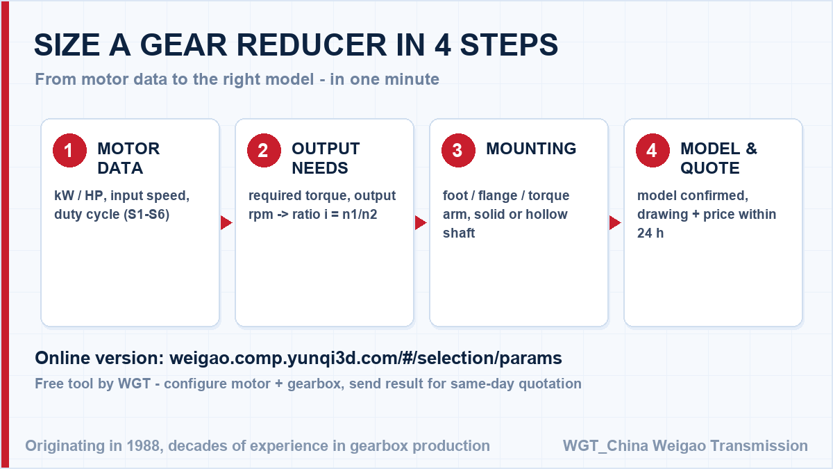
Take an 11 kW motor at 1465 rpm turning the agitator at 45 rpm. The ratio follows directly: 1465 / 45 = 32.6, so a ratio near i=32.5 is taken from the three-stage vertical band, and the frame is checked at the gel point where viscosity peaks rather than at the average of the batch. In this case frame three mounts on a torque arm clear of the steam lance and the instrument tappings, couples a solid output to the agitator through a reachable spacer, and carries a food-grade lubricant with an output seal that can be inspected without lifting the drive. The same three numbers - motor speed, target output speed, required torque - are all you need; our engineers (or the online selector below) cross-check the service factor for your duty cycle.
![gear reducer selection flow chart - ratio and frame size]()
Figure: from motor data to a confirmed gearbox model in four steps.
Common Models in the M3 Series
| Model | Centre distance | Output | Typical duty |
|---|
| M3PSF50 | size 50 | solid shaft, foot | conveyors, feeders |
| M3PSF60 | size 60 | solid shaft, foot | crushers, mixers |
| M3PSF70 | size 70 | solid shaft, foot | ball mills, shredders |
| M3PSF80 | size 80 | solid shaft, foot | kilns, heavy conveyors |
| M3PSF90 | size 90 | solid shaft, foot | mill and kiln drives |
| M3RSF50 | size 50 | solid shaft, foot, right-angle | inclined conveyors, elevators |
| M3RSF60 | size 60 | solid shaft, foot, right-angle | screw classifiers, feeders |
| M3RHF70 | size 70 | hollow shaft, foot, right-angle | agitators, drum drives |
| M3PHT80 | size 80 | hollow shaft, torque arm, parallel | shaft-mounted conveyors |
| M3RHT90 | size 90 | hollow shaft, torque arm, right-angle | heavy shaft-mounted drives |
The table below shows the M3 industrial range: P builds are all-helical on parallel axes, R builds add a bevel input stage for a right-angle drive; S / H describe the low-speed shaft and F / T the mounting.
Application Cases
Stone quarry conveyor
A stone quarry runs reducers on its primary conveyor. Shock loads from oversized rock are absorbed by the case-hardened gears (surface HRC58-62), and after two years of continuous duty the units still run within their original 68 dB noise spec.
Flour mill screw conveyors
A flour mill standardised on gear reducers for its screw conveyor network. One spare-part pool now covers fifteen drives, and the smooth helical input stage keeps noise low in the packing hall.
![industrial gearbox applications - conveyor mixer crusher wastewater]()
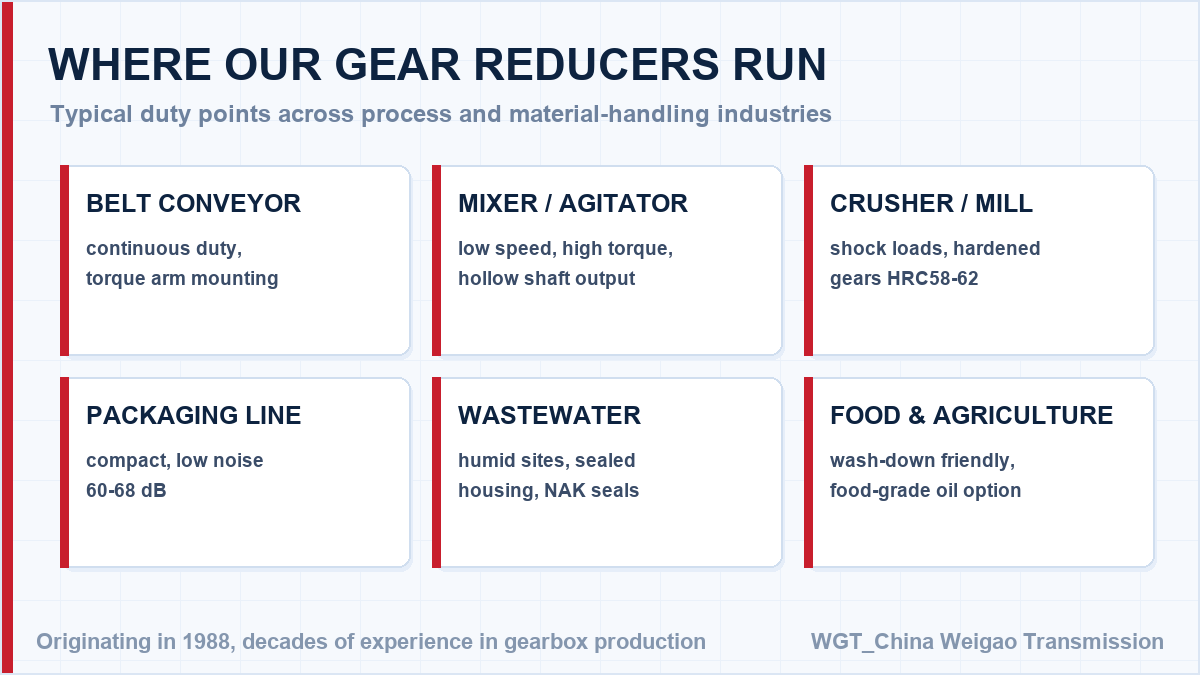
Figure: typical industries that use the WGT S-series gear reducers.
Frequently Asked Questions
Can the gear unit hold a load on an inclined conveyor?
For inclined belts a backstop prevents the loaded belt from driving the unit backwards when power is cut. Specify the incline angle when ordering so the backstop and the oil level are matched to the actual mounting position.
What is the difference between foot and torque-arm mounting?
Foot mounting bolts the housing to a foundation and suits most fixed installations. A torque-arm lets the housing swing on the driven shaft, so no base frame is needed - common on shaft-mounted conveyors where the reaction rod absorbs the torque.
Should I choose a solid or hollow output shaft?
A solid shaft with a keyed coupling is the flexible, conventional choice. A hollow shaft takes the driven shaft directly with a key or shrink disc, removing one coupling and one alignment step; it is preferred where space or alignment access is limited.
Drawings, Ratings and Test Records on Request
Need the paperwork first? Not sure which model fits? Try our online WGT Motor & Gearbox Online Selection System to match motor power, ratio and mounting in one minute.
We issue dimension drawings, rating tables and sample test records in English for your approval package, before the order is placed. Engineering and purchasing sign-off without delays. Looking for a gearbox for packaging machine? Tell us the duty point and we will confirm the model in writing.