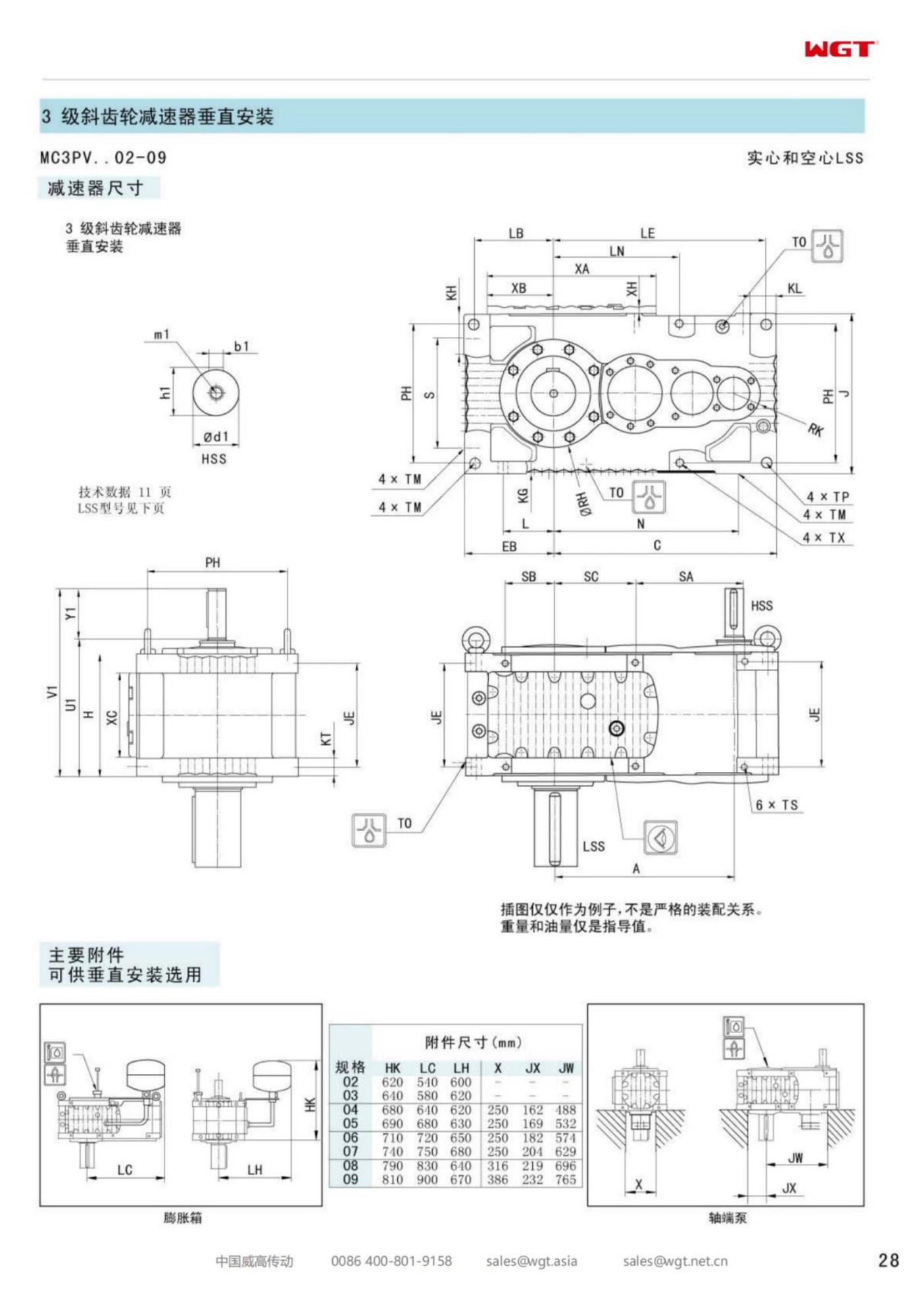
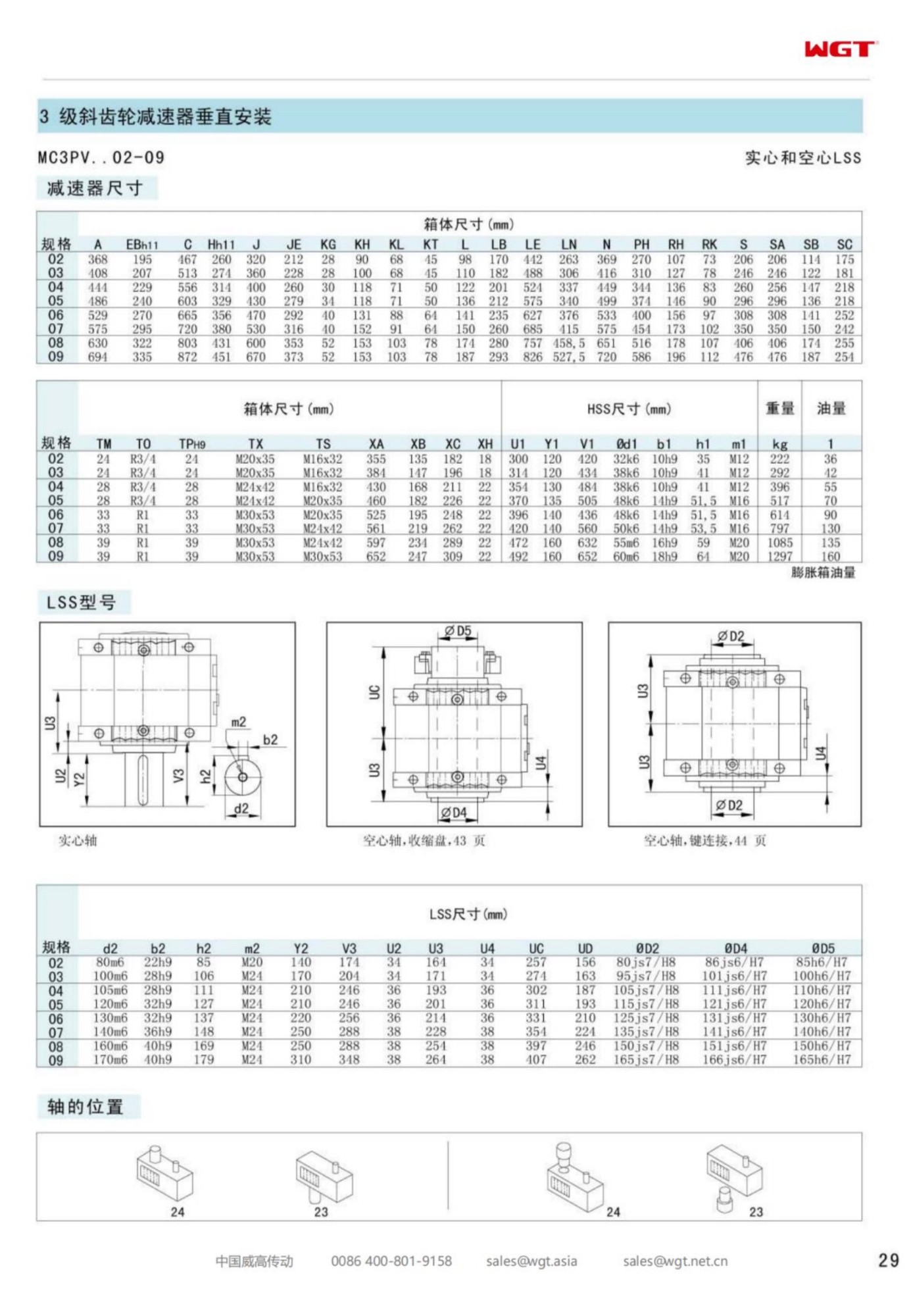
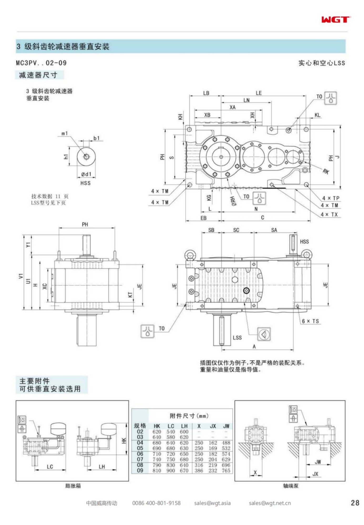
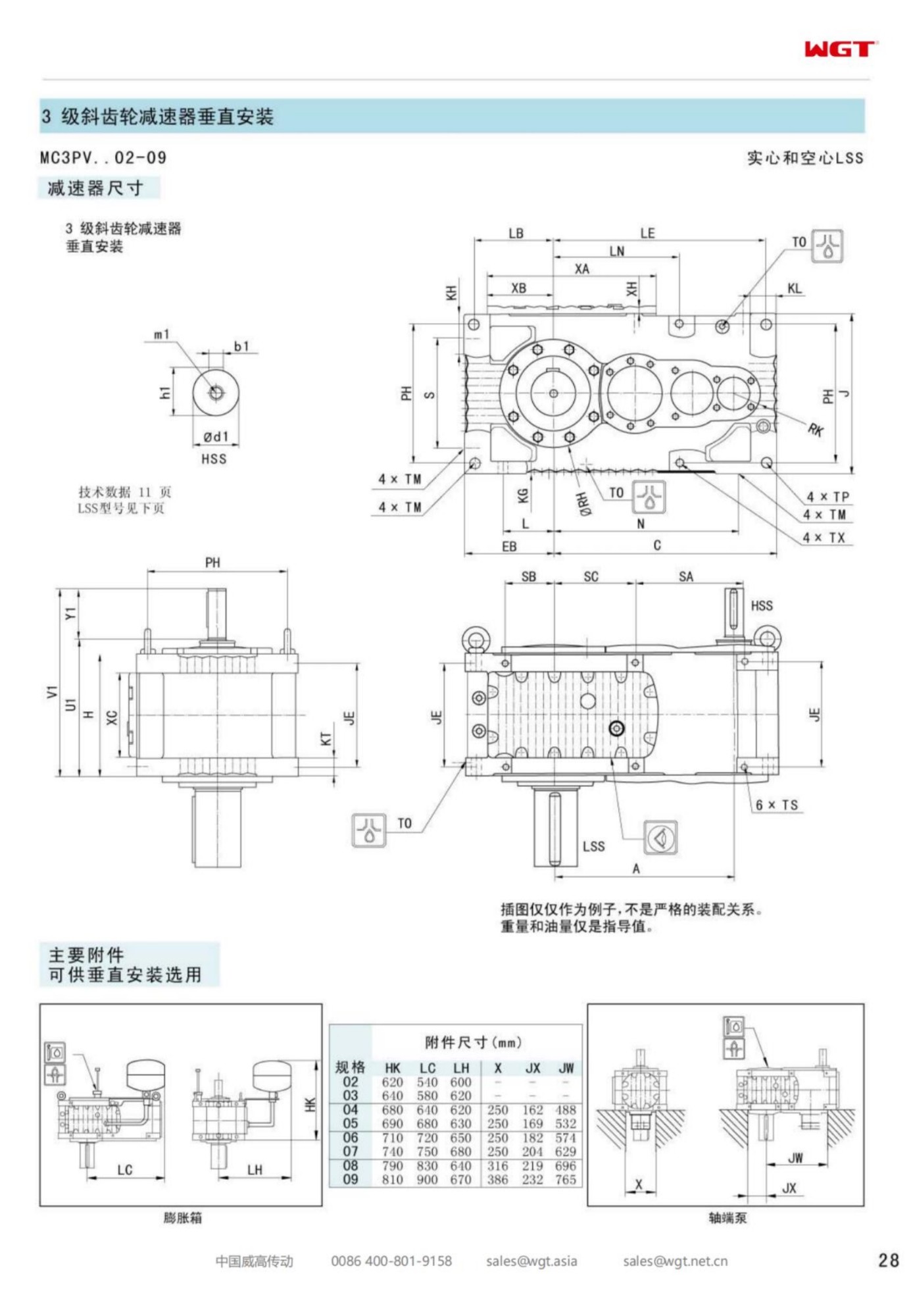
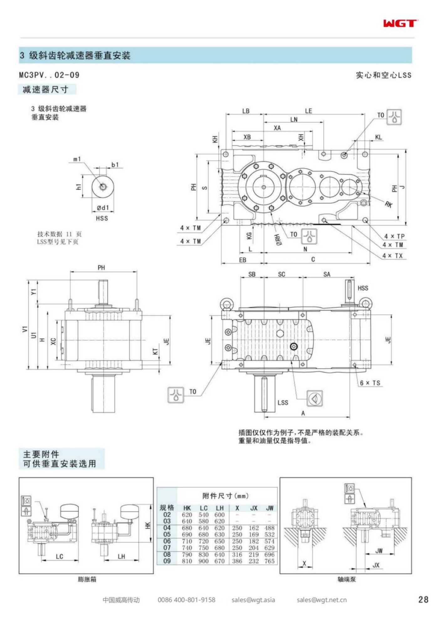
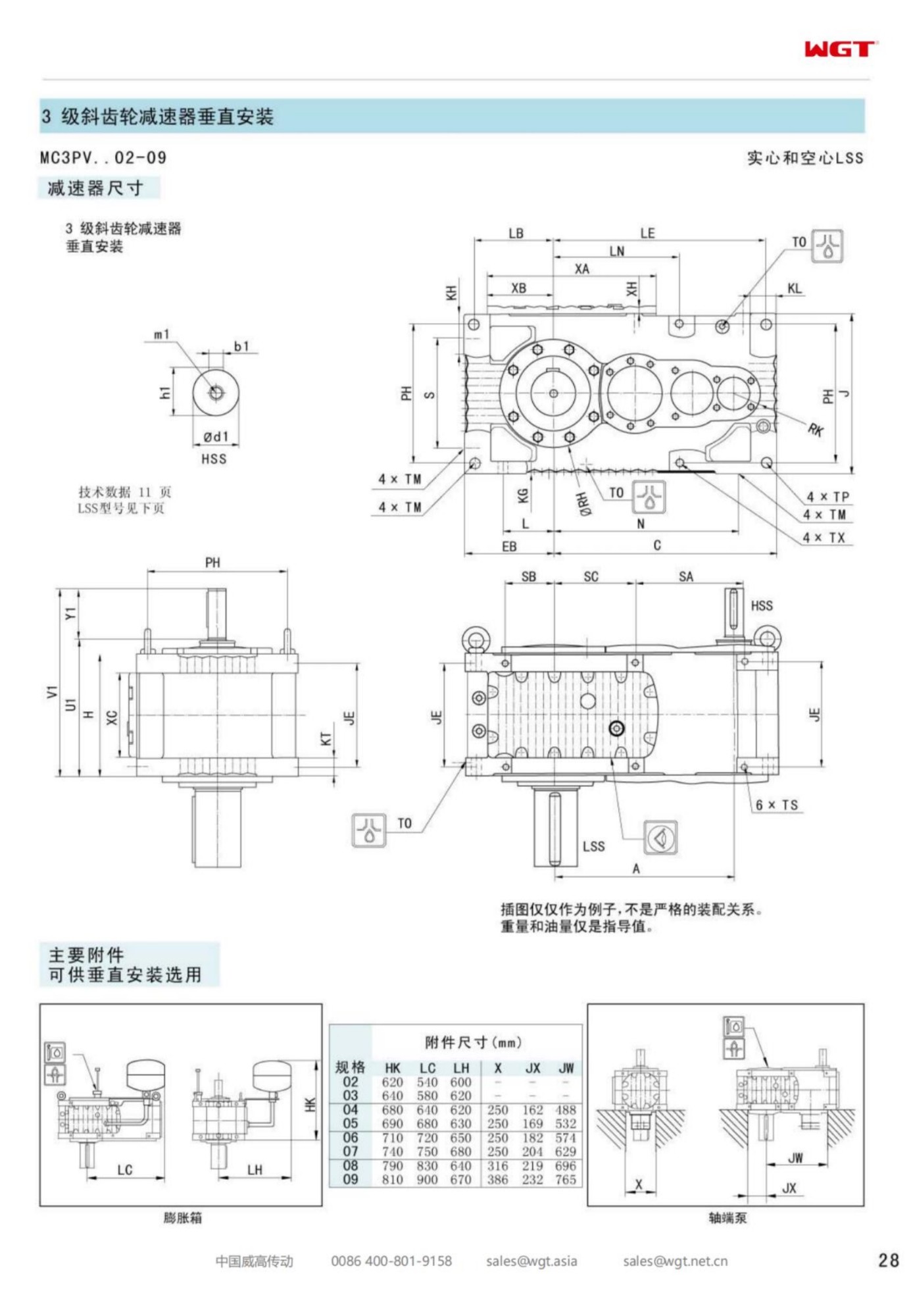
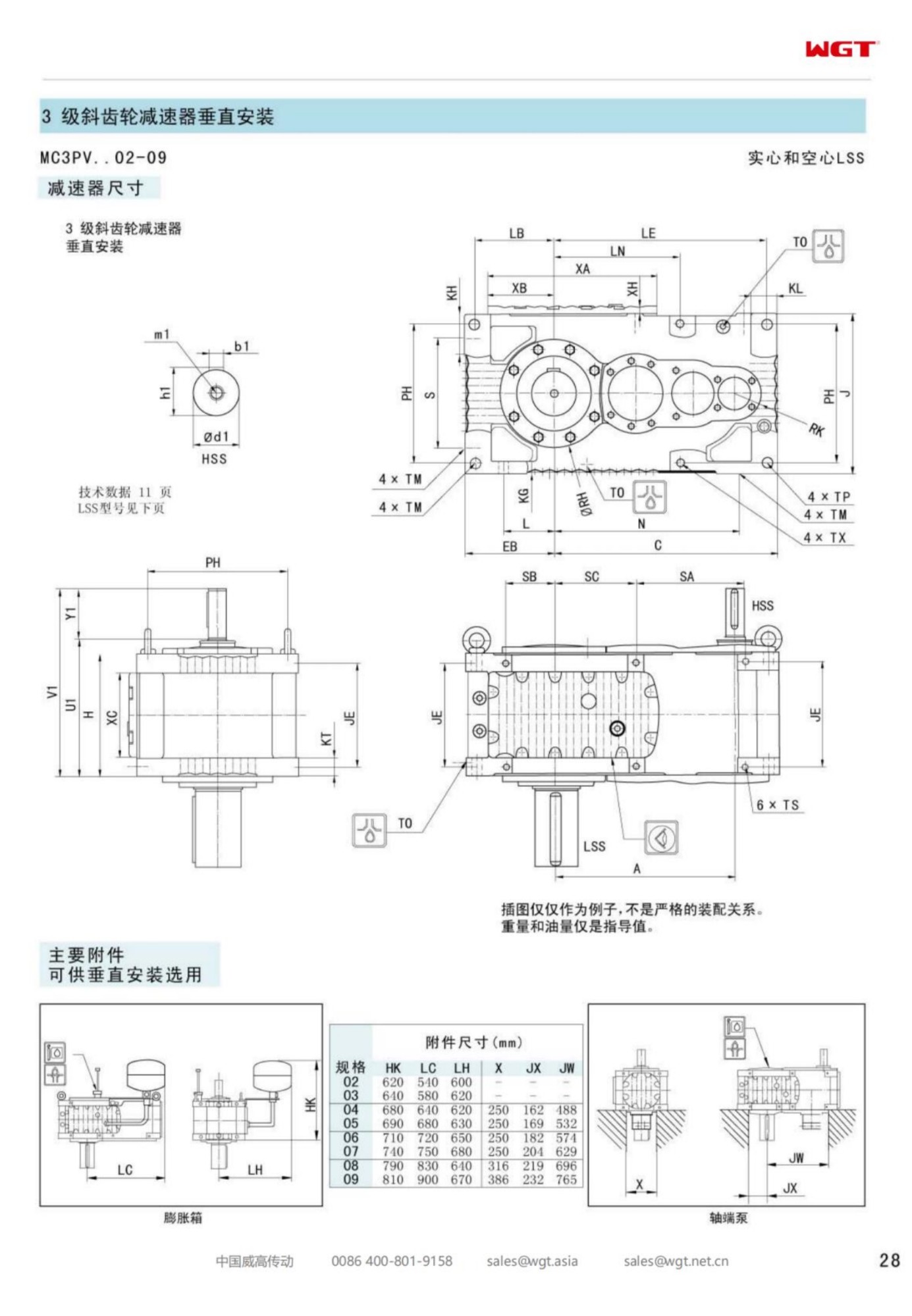
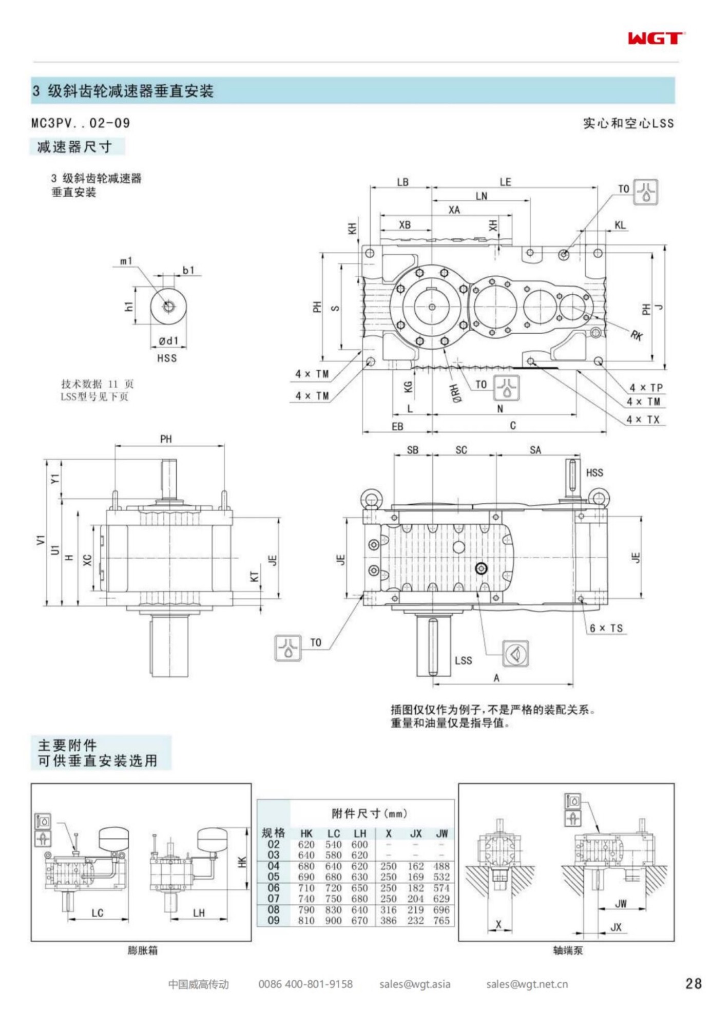
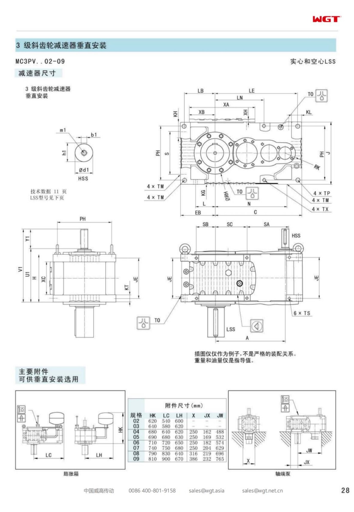
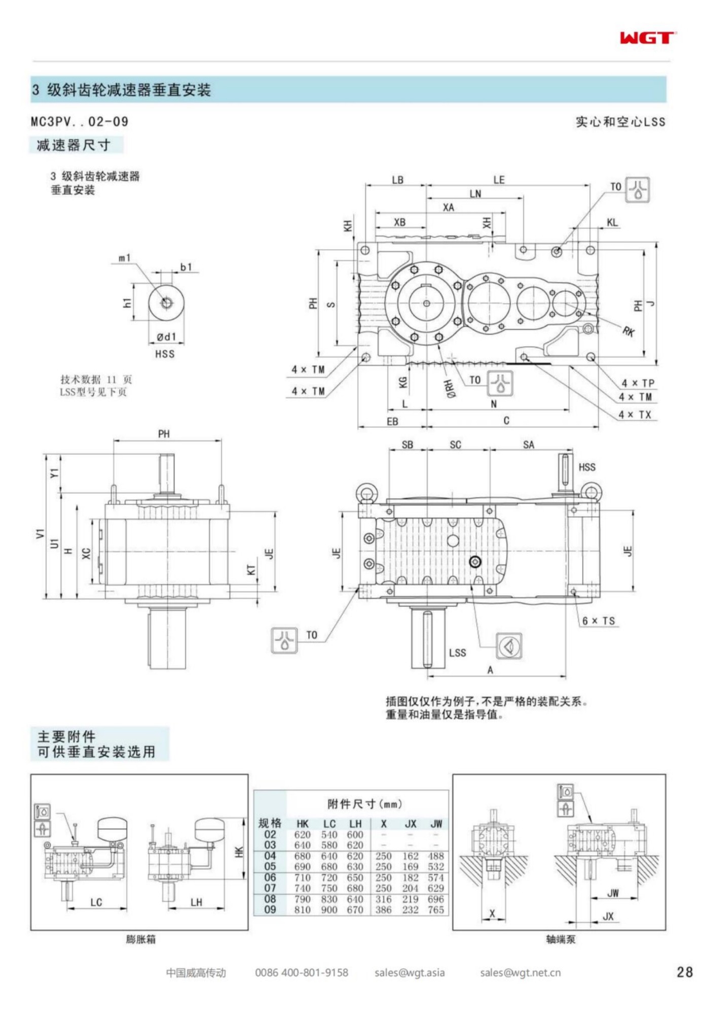
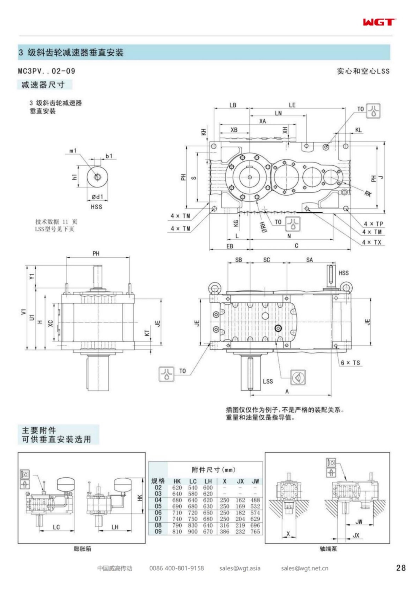
Hydrometallurgical copper circuits leach their ore in tanks that are part chemistry set and part grinder. Acid, oxidant and finely ground solids meet in a vessel held warm, and the agitator that keeps the pulp in suspension works in the middle of it. The MC3PVHF07 vertical hollow shaft gear unit drives that agitator: three helical stages in an upright case above the tank, a hollow bore through which the agitator shaft passes, and footed pads bolted to the tank bridge.
The notes that follow describe the drive in the terms a leach circuit uses: reagent attack, solids load, the atmosphere over the freeboard, and the numbers worth putting on an enquiry.
Acid, Iron and a Slurry That Grinds
Leach pulp is not a fluid with dirt in it; it is a suspension of hard particles in an aggressive liquor. The particles come from grinding, so they are angular, and the liquor carries ferric iron and free acid at a temperature the vessel holds deliberately.
Everything the pulp touches is chosen for that combination, and the agitator is no exception. The gearbox sits above the pulp rather than in it, which removes the worst of the wear but none of the consequences.
Reading MC3PVHF07 in Order
The designation is a mounting instruction written in six characters.
| MC | Industrial gear unit family built for continuous plant duty |
| 3 | Three helical reductions inside one upright case |
| P | Parallel-shaft layout, input and output on parallel axes |
| V | Vertical build, output axis pointing down into the vessel |
| H | Hollow output bore, the process shaft passes through it |
| F | Footed reaction pads, bolted to the vessel bridge or plate |
In plain terms: three-stage industrial unit, parallel shafts, vertical, hollow bore, footed pads, seventh frame of the band.
Layout Above a Leach Tank
Leach tanks are usually built in rows on a common deck, with pipework overhead and a walkway between vessels. The space above the tank top belongs to that pipework, so a drive that stands upright in the centre of the bridge has to be planned around it rather than discovered under it.
A vertical build puts the motor at the top of the case, pointing up, which keeps the footprint on the bridge to the size of the pads. It also puts the motor in the warm air rising off the vessel, and that has to be said out loud in the specification.
Load Path From Impeller to Bridge
The impeller's resistance arrives at the case as torque and as a bending moment, because a long shaft in a moving pulp never stays perfectly straight. The case takes both, and passes them to the pads, and the pads pass them to the bridge.
That chain is only as good as its weakest joint, which is usually the pad-to-steel connection rather than the gearbox. Slotting, shimming and torque values for the pad bolts belong in the erection instructions, not in a fitter's judgement on the day.
Sulphuric Mist on Case and Fasteners
Above a hot acid vessel there is always a mist layer, and the mist is the same chemistry as the liquor in a finer form. It settles on cool surfaces, and the case of a gearbox above a leach tank is a cool surface for the first hour after a shutdown.
A finish system and a fastener grade chosen for that layer cost little at order stage. Renewing a case that has grown a rust bloom in the first season costs rather more, and it always happens on the unit that is hardest to reach.
Three Stages Against a Dense Pulp
Leach agitators turn slowly enough that a single-stage unit could not reach the ratio, and a two-stage unit would come out large and heavy for the torque. Three helical stages land in the middle: a compact upright case, a ratio in the range these vessels use, and a train that carries the torque without a sliding mesh.
The absence of a worm stage also means the drive does not self-lock, which the plant usually wants: a rake or impeller that can be turned by hand during maintenance is easier to work on than one that cannot.
Bore Wear Where Solids Settle
Solids settle in any vessel that stops, and a settled bed grips whatever passes through it. The bore is above the pulp, so it does not see the bed directly, but splash and vapour carry fines upward and those fines find the clearance between bore and shaft.
A bore agreed against the real shaft, with a defined fit and a protected entry, is the practical answer. A bore chosen loosely to make assembly easy turns into a bore that wobbles, and a wobbling column wears its bearing seats long before its time.
Lubricant Life in a Hot Wet Room
The tank deck of a leach circuit is a hot, humid, mildly acidic room with no air conditioning and no shade. Oil in a case standing in it works at a temperature set by the ambient air plus whatever the gears add, and that sum is higher than a catalogue table assumes.
Synthetic oil and a breather that draws from a clean point are the two decisions that extend drain intervals in that room. A desiccant breather is not an extravagance on a vessel that vents acid mist a metre below the drive.
Seal Strategy for Acid Spray
Where oxidant is sparged into a leach tank, the surface is not calm, and spray reaches farther than the drawing suggests. An output seal that relies on a single lip is asked to keep that spray out of a bearing housing for years.
A labyrinth in front of the lip, a drain to take what gets past the first stage, and a grease-purgeable space between them is the arrangement worth specifying. It costs a little at build and saves the bearing that would otherwise fail quietly.
Oxygen Addition Changes the Mixing Duty
Leach circuits that sparge oxygen are mixing for mass transfer as well as for suspension. The impeller is chosen to disperse gas, which means a different blade form, a different power draw, and a torque curve that is not the same as a simple slurry agitator.
The gearbox selection has to be told which duty it is serving. A unit specified for suspension and then asked to disperse gas runs at a different point on its curve, and the difference shows up as heat and noise rather than as an immediate failure.
Numbers a Leach Circuit Should Supply
The enquiry should carry vessel diameter and straight-side height, pulp density and percent solids, the impeller type and diameter, the output speed, the shaft length and diameter, the sparge arrangement, the deck temperature, and the pad locations on the bridge.
It should also state how the tank is started after a shutdown: with the bed resuspended by sparge alone, or with the agitator expected to break into a settled bed. The second answer moves the frame up a size more often than any other single line on the sheet.
Frame Seven at the Leach Bay
The seventh frame sits in the middle of the vertical band and turns up on leach tanks of moderate diameter, where the pulp is dense but the shaft is not yet long enough to dominate the design.
Chosen with the bore matched to the real shaft and the case protected for the mist layer, it is a drive that holds a suspension for years without asking for attention beyond its oil checks.
Acid, iron and ground rock in a warm leach tank - the duties this frame is built for:
- Leach tank agitator at a hydrometallurgical copper plant
- Atmospheric leach vessel agitator at a copper concentrator
- Pressure leach flash vessel agitator at a base metal refinery
- Heap leach pregnant liquor agitator at a solvent extraction plant
- Raffinate tank agitator at a copper SX-EW circuit
- Bio-leach reactor agitator at a refractory ore plant
How Customers Use This Unit
Wood chipper line
A board mill drives its drum chipper with a heavy-duty gear unit. Knife engagement shocks arrive several times a second, and the case-hardened gearing with generous bearing spans has shown no measurable wear.
Fertiliser plant drag chain
A fertiliser complex runs drag-chain conveyors on industrial gear units in a corrosive atmosphere. The heavy-duty epoxy coating and FKM seals have kept the units presentable and leak-free through several campaign cycles.
What Engineers Ask Us
Do you offer a version with an integrated gear motor?
We can supply the unit as a complete gear motor with an IEC motor bolted on and tested as one assembly. That saves you the alignment and coupling work, and the whole assembly carries the same one-year warranty.
How do I know when the unit needs maintenance?
Beyond routine oil checks, watch for oil weeping at the seals, unusual noise or vibration, and any rise in housing temperature. A seal kit is inexpensive; catching a weeping seal early avoids damage to the bearings and gears.
Model Table: Frames, Shafts and Duty
| Model | Centre distance | Output | Typical duty |
|---|
| M3PSF50 | size 50 | solid shaft, foot | conveyors, feeders |
| M3PSF60 | size 60 | solid shaft, foot | crushers, mixers |
| M3PSF70 | size 70 | solid shaft, foot | ball mills, shredders |
| M3PSF80 | size 80 | solid shaft, foot | kilns, heavy conveyors |
| M3PSF90 | size 90 | solid shaft, foot | mill and kiln drives |
| M3RSF50 | size 50 | solid shaft, foot, right-angle | inclined conveyors, elevators |
| M3RSF60 | size 60 | solid shaft, foot, right-angle | screw classifiers, feeders |
| M3RHF70 | size 70 | hollow shaft, foot, right-angle | agitators, drum drives |
| M3PHT80 | size 80 | hollow shaft, torque arm, parallel | shaft-mounted conveyors |
| M3RHT90 | size 90 | hollow shaft, torque arm, right-angle | heavy shaft-mounted drives |
Larger size numbers mean higher torque capacity and larger shafts. Because interfaces follow the common industrial dimensions, a size-for-size change is the normal upgrade route for these industrial units.
Selection Example: Leach tank agitator at a hydrometallurgical copper plant
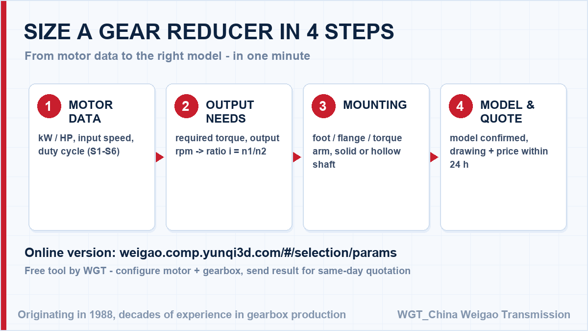
Take an 18.5 kW motor at 1470 rpm turning the leach impeller at 32 rpm. The ratio follows directly: 1470 / 32 = 45.9, so a ratio near i=46 comes from the three-stage vertical band, and the frame is sized on a restart with pulp settled after a shutdown rather than on the running suspension load. In this case frame seven sits above the leach tank on pads bolted to the bridge, carries a bore agreed against the real agitator shaft, and takes a labyrinth and drain ahead of the output lip so acid spray never reaches the bearing. Note that the ratio comes from speeds alone, while the frame size depends on torque and service factor - never size a unit on ratio only.
![industrial helical gearbox selection chart]()
A quick visual of the selection sequence for a industrial helical unit.
![M3 series gear reducer installation examples]()
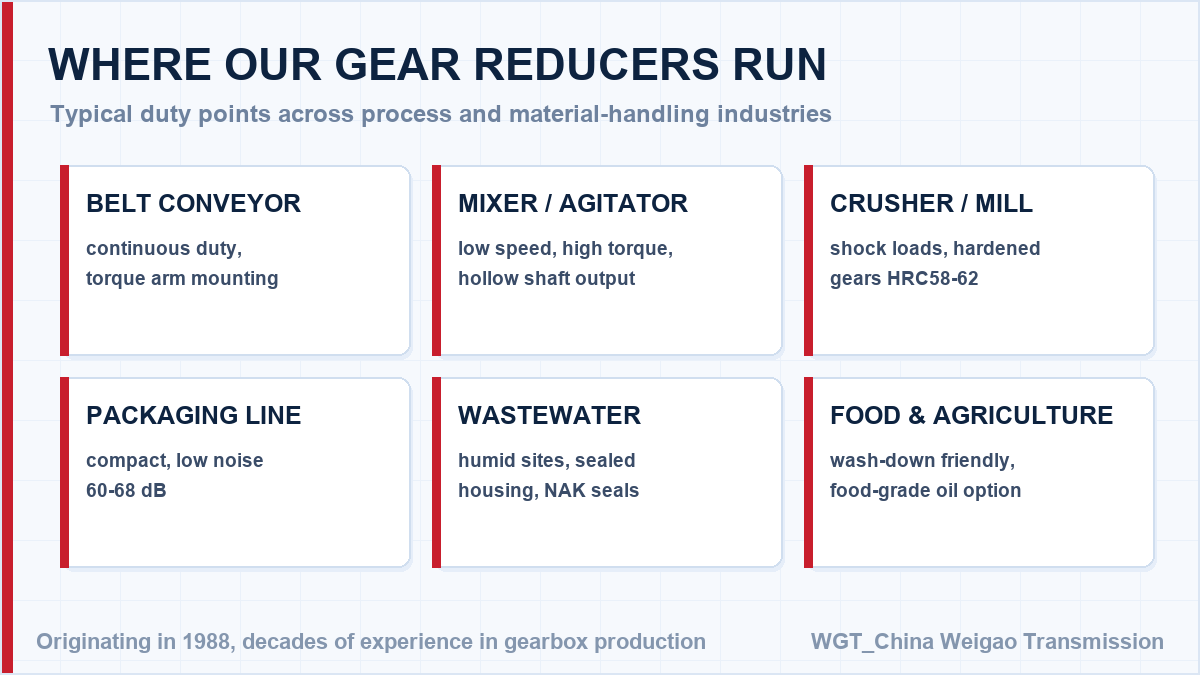
Application coverage of the the M3 series.
Shutdown Planned? Order Ahead of the Window
Beat the shutdown window. Prefer to check the figures yourself? The WGT Motor & Gearbox Online Selection System gives you the model, torque margin and ratio before you ask us.
For planned maintenance windows we reserve production capacity and ship the unit ahead of the shutdown date, so the swap takes hours instead of days. Tell us the window and we work back from it. Looking for a gear reducer for food processing machine? Tell us the duty point and we will confirm the model in writing.