


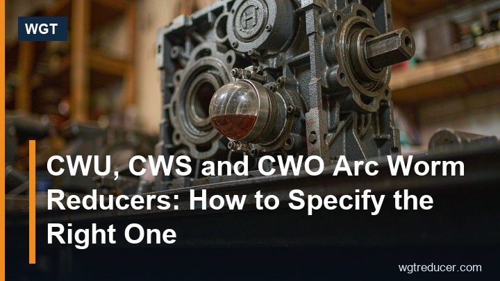
CWU, CWS and CWO Arc Worm Reducers: How to Specify the Right One
The CW family - CWU, CWS and CWO - is the arc-contact branch of the cylindrical worm reducer world, and the three letters are not marketing variants: they describe where the worm sits relative to the wheel. That single geometric choice decides the oil level, the cooling path, the maintenance access and often whether the unit survives its first year on site. Buyers who treat the letters as interchangeable end up with a gearbox that is correctly rated and wrongly installed.
This guide covers what arc contact actually changes, how to read the designation, where each worm position belongs, and which details an enquiry has to carry before a supplier can quote a buildable unit.
What Arc Contact Changes Compared With an Involute Worm
In an involute (ZI) or straight-sided (ZA) worm set, the worm profile is essentially a helical thread with a conventional flank form, and contact with the wheel is a line that migrates across the tooth as it rolls. In an arc-contact set the worm is ground with a concave profile in the axial plane, so the wheel tooth wraps around it. Contact becomes an area rather than a line, spread over a longer path.
Three practical consequences follow.
The first is load capacity. Spreading the same torque over a larger contact area lowers the contact stress, so an arc set of a given centre distance can carry more than an involute set of the same size, or carry the same load in a smaller housing.
The second is oil film formation. The concave flank helps entrain lubricant into the mesh instead of wiping it away, which improves the boundary lubrication condition at low speed and during starting - the moments when a worm drive is most vulnerable.
The third is sensitivity to alignment and to the wheel material. Because the contact pattern is wider, an arc set tolerates slightly more deflection under load, but it also demands a properly matched bronze wheel and a correct lapping or running-in procedure. A replacement wheel that is dimensionally right but metallurgically wrong will destroy the advantage.
The Letters U, S and O: Worm Position, Not Model Variant
The suffix letter states where the worm shaft sits in relation to the wheel axis.
| Build | Worm position | What it suits | What to watch |
|---|---|---|---|
| CWU | Below the wheel | Low drives, machines where the input comes from underneath | Oil level sits above the worm, so seals see full head pressure |
| CWS | Above the wheel | Most horizontal floor-mounted installations | Best heat rejection and easiest inspection access |
| CWO | Beside the wheel | Side-entry layouts, compact machine frames | Cooling depends on the exposed side; check airflow |
The distinction matters because the oil volume, the breather position and the oil level plug are set for the position ordered. A CWU and a CWS with the same centre distance and ratio are the same gear set in different arrangements, but the oil fill and the seal loading are not interchangeable.
CWS is the usual default for a floor-mounted drive: the worm sits high in the oil, the housing offers the largest free surface for heat rejection, and the inspection cover is reachable. CWU is chosen when the machine forces the input low, as on lifting equipment and machines with the motor below working level. CWO covers side-drive arrangements where neither of the other two fits.
Reading a CW Designation in the Right Order
A complete CW order string carries four pieces of information: the family letters, the centre distance, the ratio, and the mounting or shaft variant. Reading them in that order prevents most order errors.
The centre distance - the distance between worm axis and wheel axis - sets the physical size class. A larger centre distance means a larger wheel, a longer contact path and a higher torque capacity, along with larger shaft diameters and a wider bolt pattern. In the CW family the available steps run from roughly 80 mm up to about 500 mm, which covers duties from a small conveyor to a heavy metallurgical drive.
The ratio follows from the process. Motor speed divided by required output speed gives the nominal ratio, which is then rounded to the nearest manufactured step. Single-stage CW units cover a wide band; where the required reduction sits beyond it, a two-stage combination - helical first, worm second - keeps the worm set in its efficient region instead of pushing one deep reduction.
The final element is the shaft and mounting variant: solid output shaft, hollow output bore with a keyway, hollow bore with a shrink disc, flange output, or a torque-arm build. On shaft-mounted versions the unit hangs on the driven shaft and the torque arm takes the reaction, which removes both the foundation and the coupling from the installation.
Ratio, Efficiency and the Heat Balance
Worm gearing is efficient in the middle of its ratio range and progressively less so at the top, because the lead angle falls and sliding velocity dominates. Arc contact improves on the involute case, but it does not repeal the physics: a very deep single-stage reduction generates more heat per unit of transmitted power than a moderate one.
That matters on three kinds of duty. Continuous duty above roughly half the unit's rated power, high ambient temperature, and installations where the housing sits in still air inside an enclosure. On any of those, the honest approach is to give the supplier the duty cycle and the ambient and ask for a thermal check against them, rather than comparing nominal ratings alone.
Where the check comes back tight, the usual remedies are a larger centre distance, a fan on the worm shaft extension, or an oil cooler on the larger frames. Each adds cost and each is cheaper than a unit that runs at its thermal limit from the first week.
Lubrication: Grade, Level and Position
The oil does three jobs in a worm reducer: film formation at the mesh, heat transport to the housing wall, and corrosion protection during idle periods.
Grade selection follows ambient temperature rather than preference. A mineral worm-reducer oil of the correct viscosity band suits normal industrial conditions; a synthetic fill extends drain intervals and holds viscosity better where starts are cold or the surroundings are hot. Mixing grades during top-up is the most common way to lose the benefit of either.
Level depends on the mounting position, which is why the position has to be stated at order stage. The correct level is the one that puts the worm and the lower part of the wheel into the oil without submerging the seals. Overfilling raises housing pressure, pushes oil past the seals and can foam; underfilling starves the upper bearing and the wheel rim.
Backlash, Running-In and Wheel Wear
Worm sets are lapped in pairs, and the backlash measured at the output shaft belongs to that pair. During the first weeks the contact pattern settles and backlash grows slightly; after that it stays essentially stable until the bronze wheel wears.
This has two practical consequences. First, keep the running-in oil change: the first drain removes the fine bronze and iron particles generated while the surfaces mate, and it is the cheapest maintenance action in the whole life of the unit. Second, do not attempt to remove normal backlash by shifting the wheel carrier unless the manufacturer's procedure says so - the adjustment changes the contact pattern, and a mispositioned wheel wears fast and unevenly.
Wear is best monitored by backlash measurement at fixed intervals, taken the same way each time, rather than by listening for noise. A gradual, slow increase is normal. A step change after a specific event - an overload, a jam, a motor change - is the signal to open the inspection cover.
Where the CW Family Gets Specified
The family turns up wherever a right-angle drive has to be compact, quiet and reasonably priced at moderate power.
Typical duties include screw and belt conveyors in minerals and bulk handling, agitators and mixers in water and chemical plants, rotary valves and feeders, gate and sluice drives in hydro and irrigation works, lifting and winch mechanisms, and general machinery drives in metallurgy and construction equipment. In most of these the duty is intermittent or moderate, the space is constrained, and a right-angle output is a requirement rather than a convenience - exactly the conditions the family was developed for.
Where the load runs continuously at high power, or where backlash has to be minimal, a helical or bevel-helical unit is the better engineering answer, and the honest supplier will say so.
For a shaft-mounted comparison in the neighbouring helical-worm family, the SA107 hollow shaft gear unit shows how a hollow bore with a torque arm is packaged for machines without a foundation, while the S67 helical worm gearbox covers the foot-mounted general-purpose build. Where the ratio or the power falls outside a single worm stage, the online selection system shows which frame and stage combination lands inside the rating.
The Enquiry Details That Decide the Build
A quotation that can be turned into an order without a second round needs the following. Motor power, speed and starting method; required output speed or the ratio; absorbed torque or power at the driven machine; the mounting position and which of U, S or O applies; the output form - solid shaft, hollow bore, flange, torque arm; ambient temperature, dust, washdown and any hazardous-area classification; hours per day and starts per hour; and any dimensional constraint such as centre height, bolt spacing or available envelope.
Add paint specification, nameplate language and documentation requirements, and the picture is complete. With those on the table the centre distance, ratio and variant are fixed in one exchange.
Frequently Asked Questions
What is the difference between CWU, CWS and CWO?
They differ in where the worm shaft sits relative to the wheel: CWU has the worm below, CWS above, CWO at the side. The gear set can be identical, but the oil level, breather and seal loading are set for the ordered position, so the three are not interchangeable on site.
Is an arc-contact worm reducer more efficient than an involute one?
Generally yes at the same centre distance and ratio, because the concave worm profile spreads contact over an area and helps entrain oil into the mesh. The gain does not remove the basic penalty of high-ratio worm gearing, so very deep single-stage reductions still run hotter than a two-stage alternative.
Can a CW reducer be mounted vertically?
Only if it is ordered for that position. The oil fill and plug locations are arranged for the mounting orientation, and a unit filled for horizontal installation will be over- or under-lubricated when turned. State the orientation on the enquiry and confirm it on the drawing.
How often should the oil be changed?
Follow the manufacturer's interval for the ambient and duty, and always bring the first change forward to clear running-in debris. On a dusty or hot site the interval shortens; where oil analysis is available, sample at the interval and let condition decide rather than the calendar alone.
Why does backlash matter on a worm reducer?
Backlash at the output decides positioning accuracy and shock loading on reversing duty. New units carry a specified backlash measured on the lapped pair; it grows slightly during running-in and then stays stable until the bronze wheel wears. Measure it at fixed intervals rather than judging by sound.
