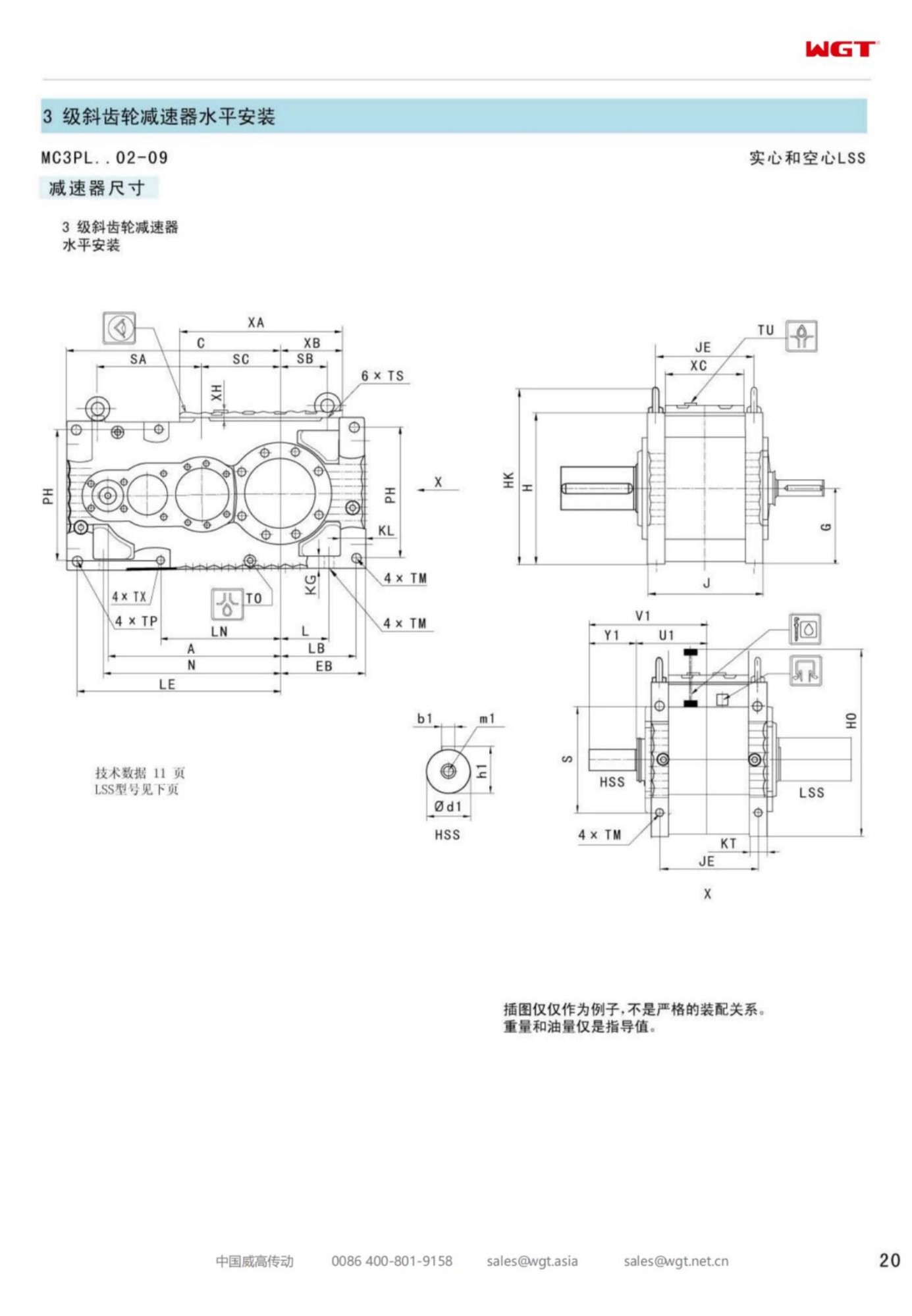
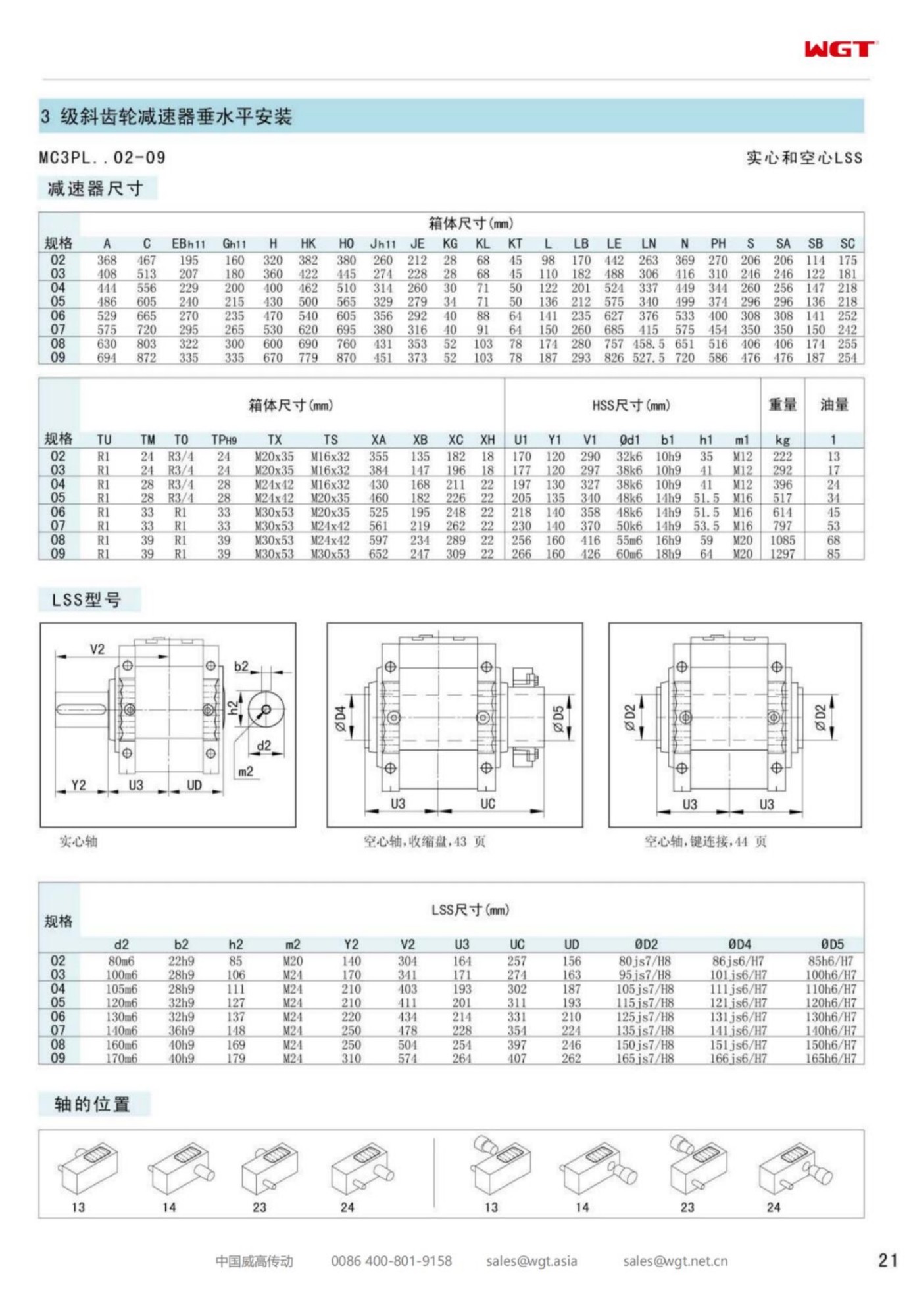
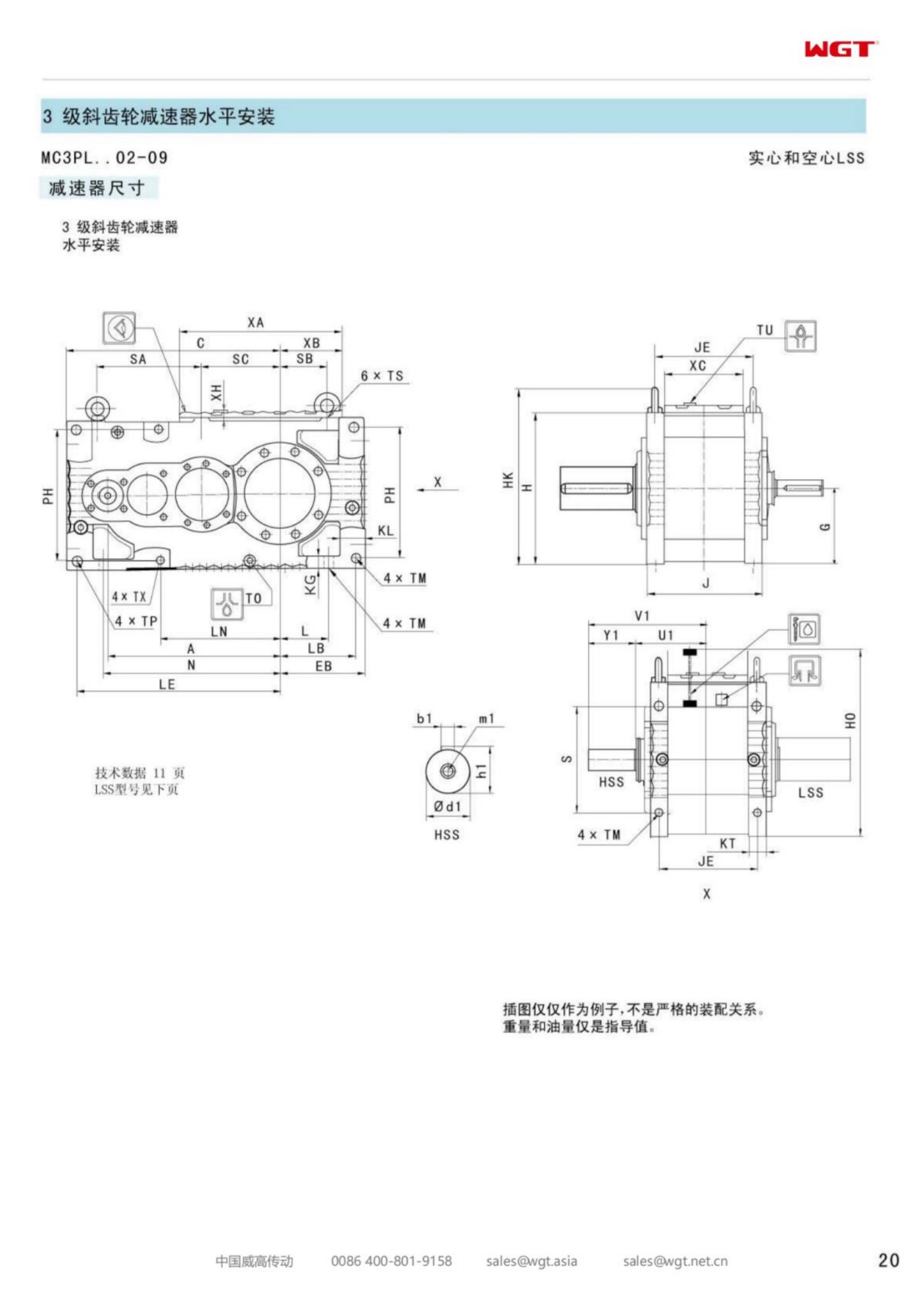
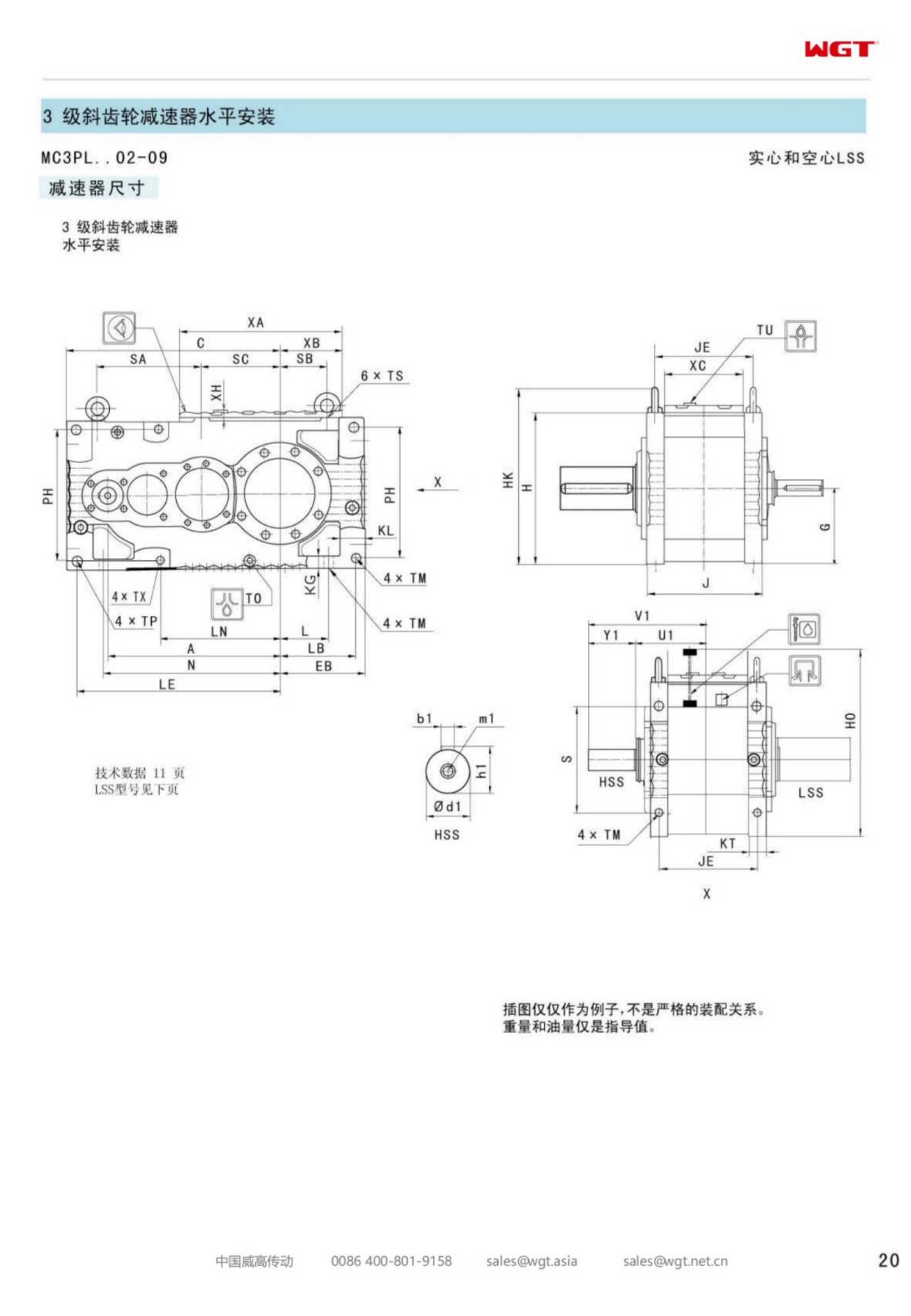
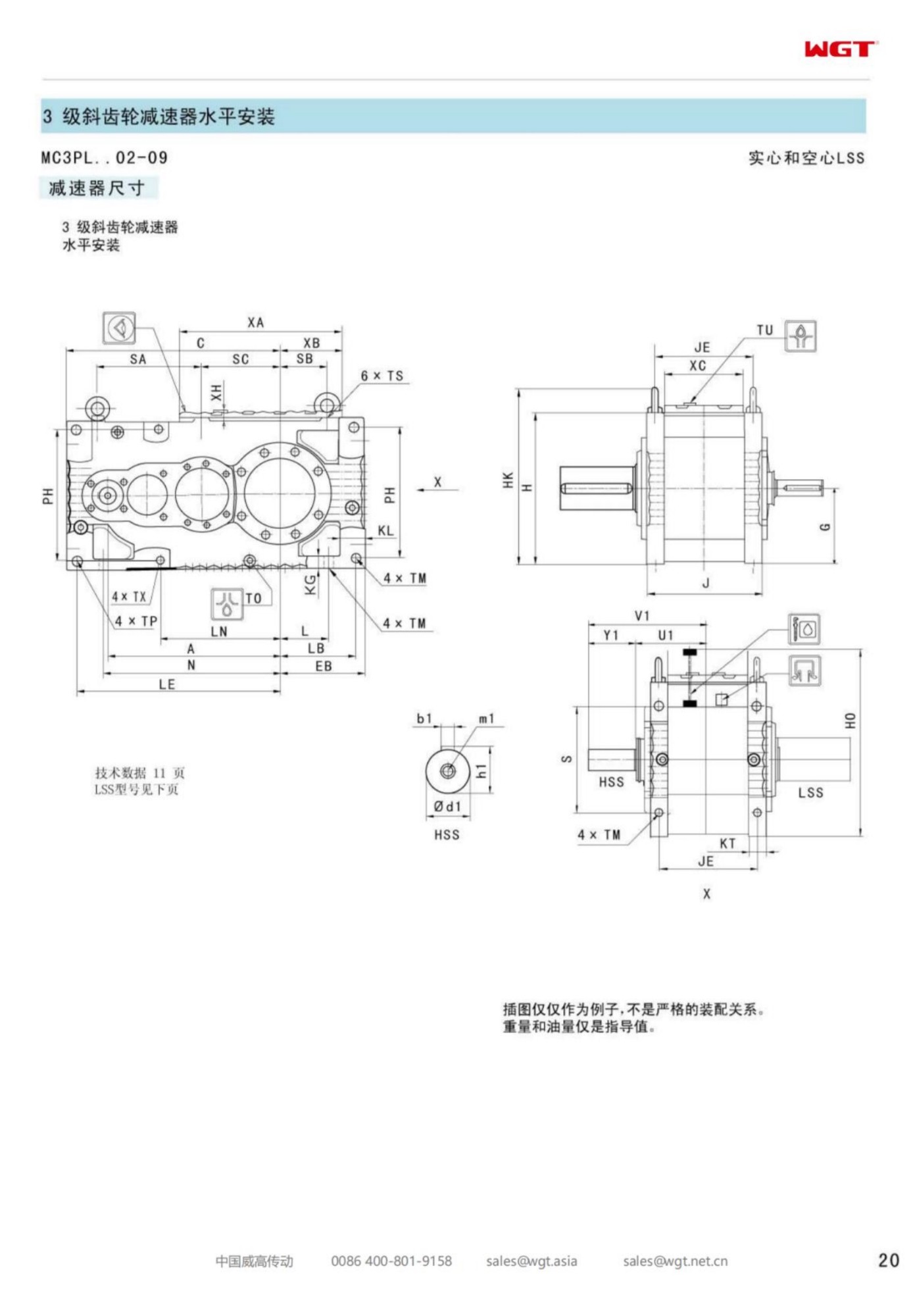
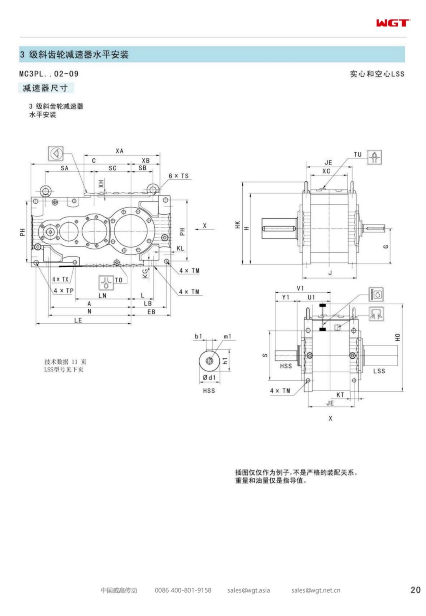
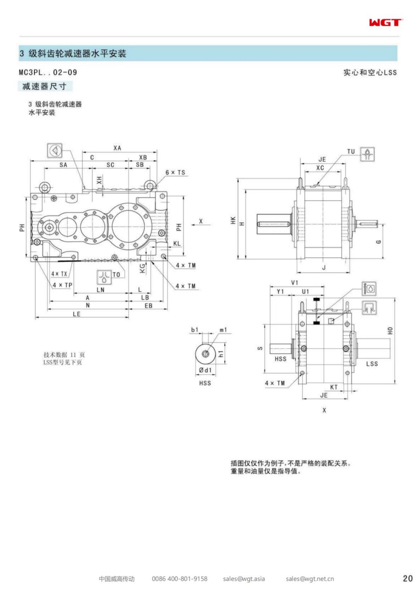
A sand mixer is a slow machine in a dirty room. Green sand, bentonite and a little moisture turn over under steel ploughs for a few minutes per batch, the motor starts and stops with the cycle, and fine clay dust settles on everything that stands still. The MC3PLHF07 parallel shaft gear unit is built for that seat: three helical stages, a level output axis, a hollow bore over the muller shaft and a foot plate that bolts to the mixer frame.
The sections below explain what the code fixes, how the bore and the foot plate share the reaction, and what a foundry states on the enquiry so the drive matches the batch cycle it has to survive.
Sand Mixing Punishes Slow Drives
Mixing is a torque job, not a speed job. The ploughs drag through a bed that resists differently in every part of the trough, so the load oscillates once per revolution on top of a high average. A drive selected on average torque alone will run hot and short; one selected with the peak of that oscillation in mind runs dull and long. That single distinction decides the frame.
Reading the MC3PLHF07 Code
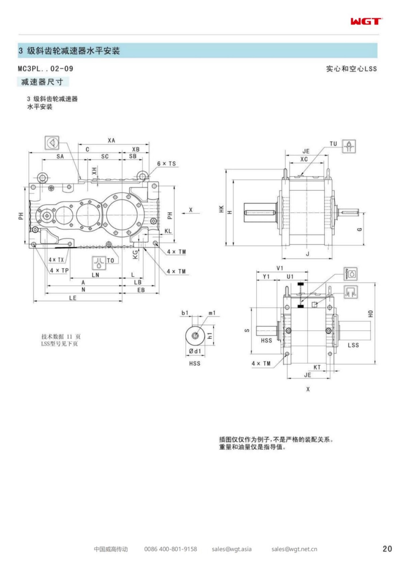
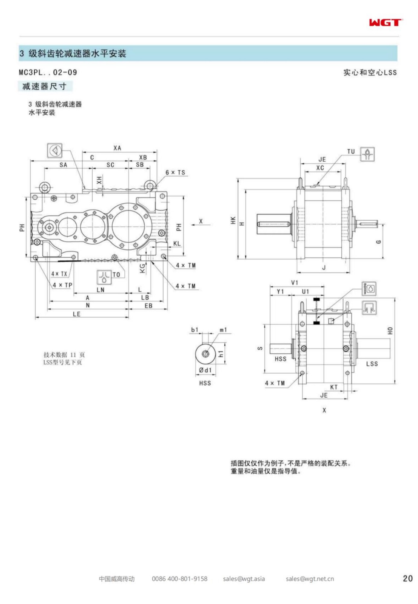
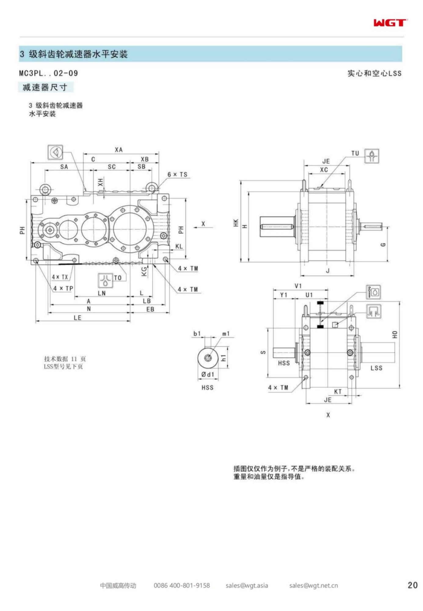
The designation is a layout already decided, letter by letter.
| MC | Industrial gear unit family for continuous plant duty |
| 3 | Three stages of reduction in one housing |
| P | Parallel-shaft helical gearing, coaxial input and output |
| L | Level output axis into the muller shaft |
| H | Hollow output bore over the mixer shaft |
| F | Foot mounting on the mixer frame |
| 07 | Seventh frame of the three-stage band |
In plain terms: a three-stage industrial unit, parallel shafts, level axis, hollow output, foot-mounted, in the seventh frame of the band. Nothing in the string needs translating into a drawing before the mounting can be visualised.
A Hollow Bore on the Muller Shaft
The muller shaft carries the plough arms and passes through the trough end wall, which is exactly where a bore earns its keep. The shaft enters the output directly, the drive hangs on it, and the outboard bearing in the trough wall takes the radial work. Changing a plough arm becomes a lid-off job rather than a drive-off job.
A Foot Plate on a Foundry Floor
Foundry floors are solid and the mixer frames that sit on them are heavy, so a foot mounting has somewhere honest to push against. The plate has to be flat and shimmed rather than pulled down onto a rough weld, because a case twisted at its feet will leak at the output seal within a season. Four bolts, a straightedge and one shim pack are the whole installation.
Dust, Binder and Heat Around the Mixer
Clay dust is fine enough to travel and sticky enough to stay. It finds breathers, settles on cooling surfaces and turns into a paste wherever a trace of oil appears. Heat from the mixed sand and from the compact motor adds a second stress. A drive with a breather sited away from the dust plume, covers that seal after every service, and a case that can be wiped down is worth more here than an extra rating step.
Batch Starts and the Torque They Ask For
A mixer does not start empty. It starts with a bed already in the trough, often a bed that has stood long enough to settle. Breakaway torque therefore sits well above running torque, and it repeats many times a shift. Sizing has to take the restart condition as the design case and treat the running load as the easy half of the duty.
Keeping Binder Out of the Seal
Bentonite and oil meet at the output seal and make a grinding paste if they are allowed to. A protected seal arrangement, a slinger that throws material off the shaft, and a drain that lets the trough be cleaned without flooding the seal are the three practical answers. All three cost less than one seal change with the trough full of sand.
Three Stages for a Muller's Slow Turn
Plough shafts turn slowly, and the ratio needed from a four-pole motor lands squarely in the three-stage band. Three meshes share the reduction without asking any single stage to do unreasonable work, and the resulting case still fits the space beside the trough that the foundry layout left for it.
Service Access in a Moulding Bay
Moulding bays are crowded, and the space beside a mixer is usually the space the sand conveyor already occupies. Specifying the inspection side, the drain plug position and the lifting points before the order is placed is the difference between an oil change that takes twenty minutes and one that takes a shift and a crane.
From Batch Weight to Output Speed
Batch weight and mix time give the plough speed the process needs, and that speed with the motor speed fixes the ratio. Torque follows from the bed resistance at the worst point of the cycle, adjusted by the service factor the foundry's own history justifies. Two numbers in, one frame out - and the arithmetic is done before the enquiry is sent, not after.
What a Foundry Puts on the Enquiry
The useful first message lists the muller shaft diameter and keyway, the plough speed and batch cycle, motor frame and speed, the binder system in use, and whether the trough is cleaned wet or dry. Add the ambient temperature and a photograph of the mounting pad, and the quotation comes back with a mounting drawing instead of a question.
Frame Seven in a Moulding Line
Frame seven covers the mixers that feed a real moulding line: big enough to take a settled bed at restart without running hot, compact enough to sit against the trough wall, and bored for a shaft that carries ploughs rather than a coupling. On a line where the mixer sets the pace, that is the frame the shift pattern asks for.
Clay dust, a settled bed at every restart and a slow plough - three stages take the strain:
- Green sand mixer in an iron foundry
- Batch muller on a moulding line
- Sand reclamation mixer at a steel foundry
- Core sand mixer in a core shop
- Continuous mixer feeding a moulding station
- Sand cooler discharge paddle shaft
Model Range and Centre Distances
| Model | Centre distance | Output | Typical duty |
|---|
| M3PSF50 | size 50 | solid shaft, foot | conveyors, feeders |
| M3PSF60 | size 60 | solid shaft, foot | crushers, mixers |
| M3PSF70 | size 70 | solid shaft, foot | ball mills, shredders |
| M3PSF80 | size 80 | solid shaft, foot | kilns, heavy conveyors |
| M3PSF90 | size 90 | solid shaft, foot | mill and kiln drives |
| M3RSF50 | size 50 | solid shaft, foot, right-angle | inclined conveyors, elevators |
| M3RSF60 | size 60 | solid shaft, foot, right-angle | screw classifiers, feeders |
| M3RHF70 | size 70 | hollow shaft, foot, right-angle | agitators, drum drives |
| M3PHT80 | size 80 | hollow shaft, torque arm, parallel | shaft-mounted conveyors |
| M3RHT90 | size 90 | hollow shaft, torque arm, right-angle | heavy shaft-mounted drives |
Frame sizes in this series follow a widely used industrial dimension ladder: foundations, couplings and guards of the existing installation are reused as they are.
Proven Installations
Airport baggage conveyor
An airport baggage-handling integrator uses reducers on check-in conveyors. Thousands of start-stop cycles a day are absorbed without overheating, and the low noise level matters in a public terminal.
Quarry primary crusher
A quarry operator fits industrial gear units on its primary jaw crusher feeders. The shock of rock dumped straight from the haul truck is covered by the service factor, and the cast-iron housing shrugs off years of dust and vibration.
![gearbox applications in quarry food and water plants]()
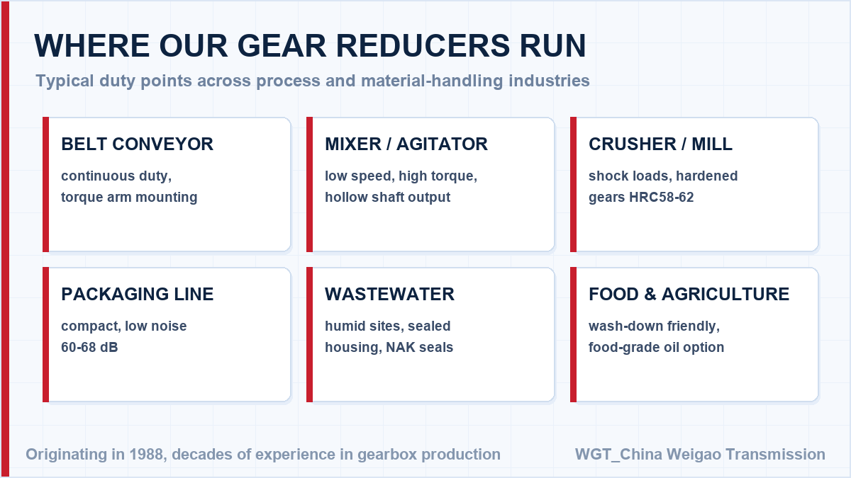
Conveyor, mixer, crusher and wastewater duties share the same gear family.
Selection Example: Green sand mixer in an iron foundry
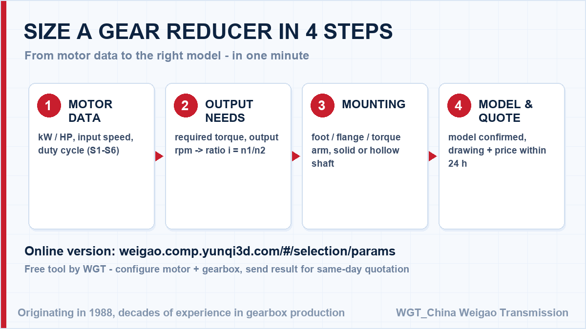
Take a 15 kW motor at 1460 rpm turning the muller shaft at 17 rpm. The ratio follows directly: 1460 / 17 = 86, so a ratio near i=86 comes out of the three-stage parallel band, and the frame is confirmed against the restart of a bed that has stood through a shift change rather than against the running mix load. In this case frame seven takes the batch from a case bolted to the mixer frame, hangs on the muller shaft through a bore, and keeps binder dust out of its seal and breather. Motor speed over target speed gives the ratio; the driven machine decides the service factor, and the two together decide the model.
![industrial gear unit sizing procedure diagram]()
The four inputs the online selector asks for.
Engineering Support Before You Buy
Unsure about the frame size? Work out the ratio, torque and frame size yourself with the WGT Motor & Gearbox Online Selection System, then send the result - we confirm it in writing.
Our selection engineers check every enquiry against the rating tables, including shock class and daily running hours. You get the calculation, not just a part number - at no charge and with no obligation. Looking for a gear motor for car wash system? Tell us the duty point and we will confirm the model in writing.
FAQ: Selection, Mounting and Maintenance
What happens if my duty changes after installation?
Send us the new duty point. A revised torque and service-factor calculation is free of charge, and the answer is usually one of three: the unit is fine, add an oil change interval, or plan a frame change at the next shutdown.
Can this unit mount on my existing installation without redesign?
Yes - the series is manufactured to the same centre distances, shafts and flange dimensions of the common industry frames, so couplings, guards and foundations stay untouched.