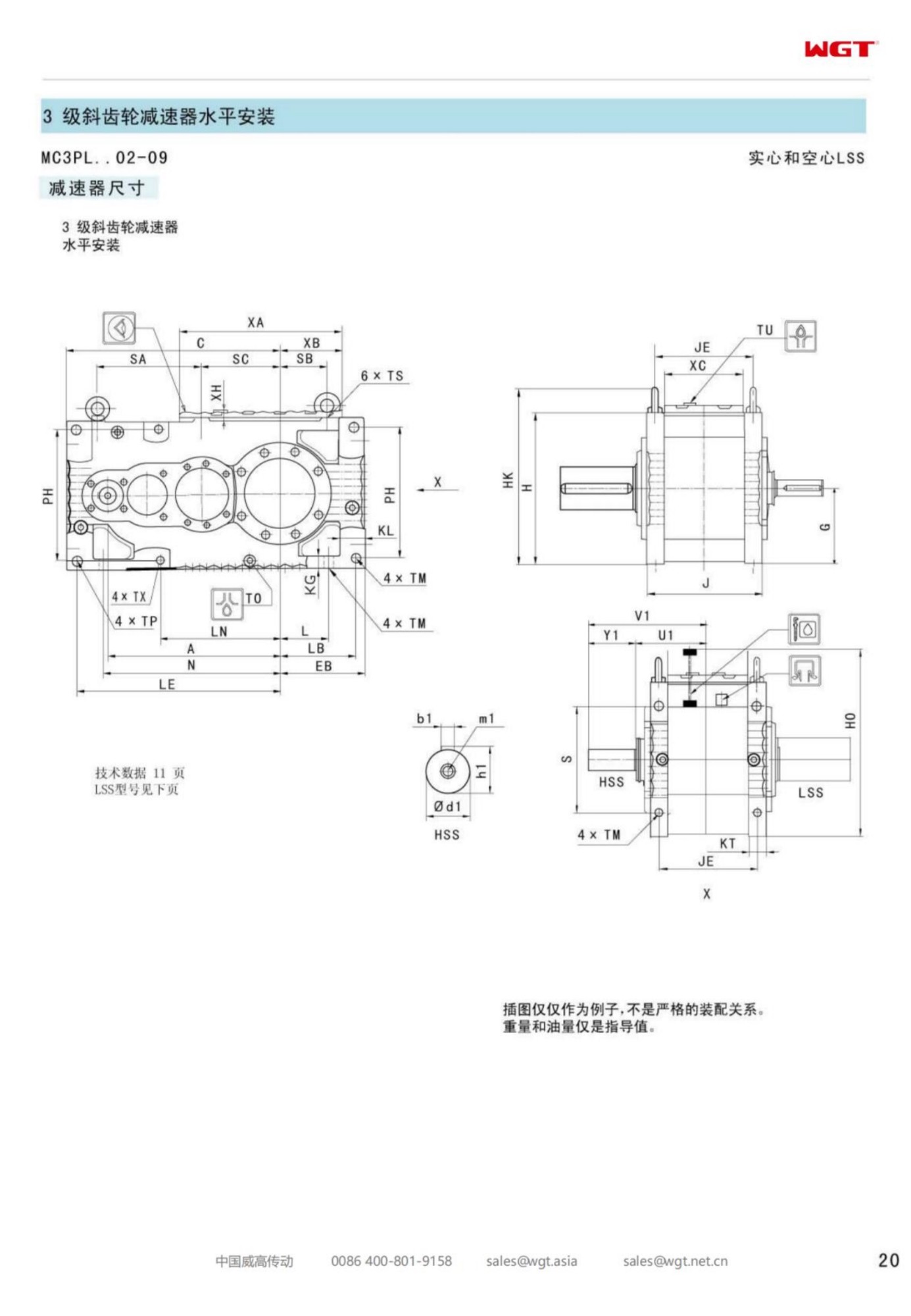
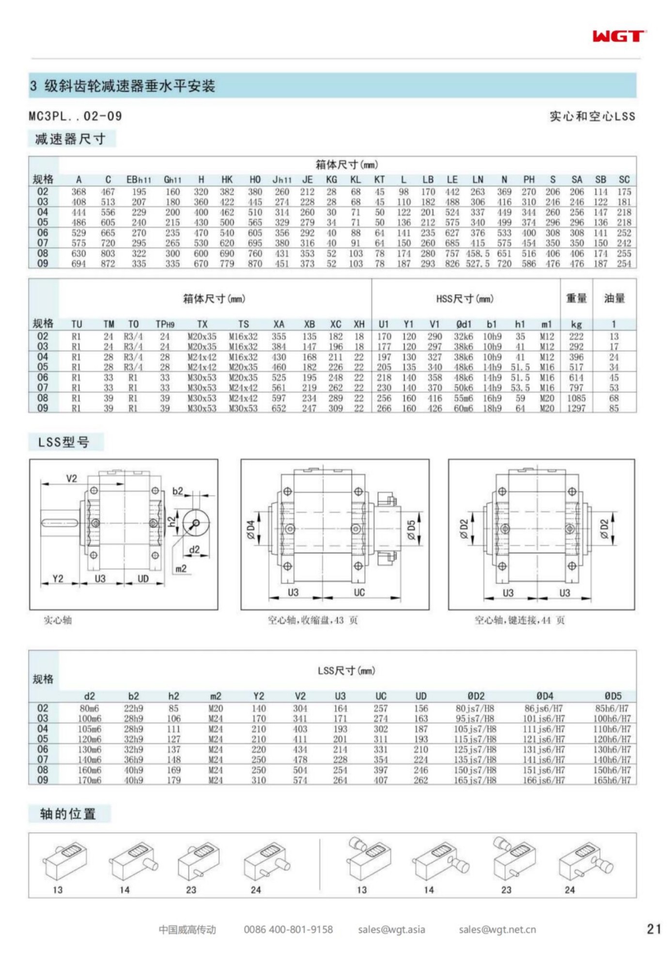
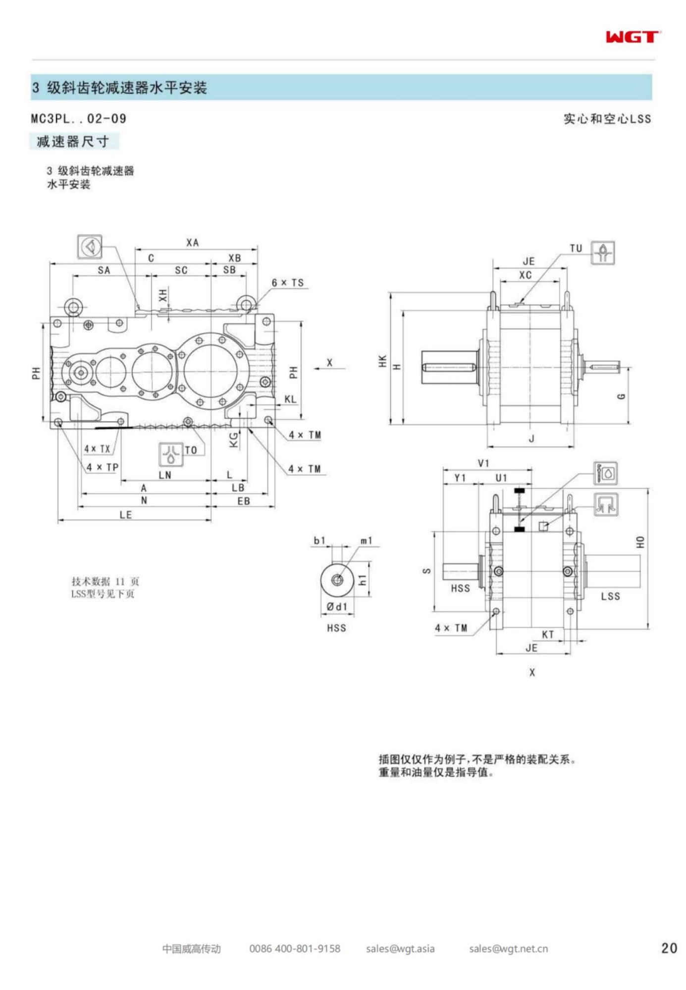
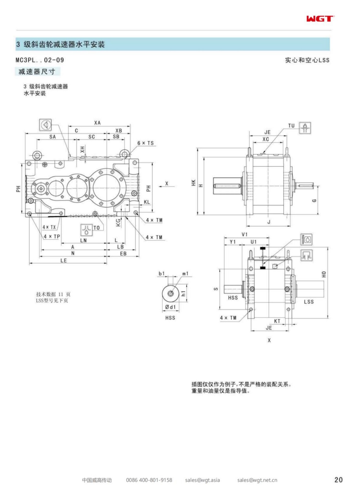
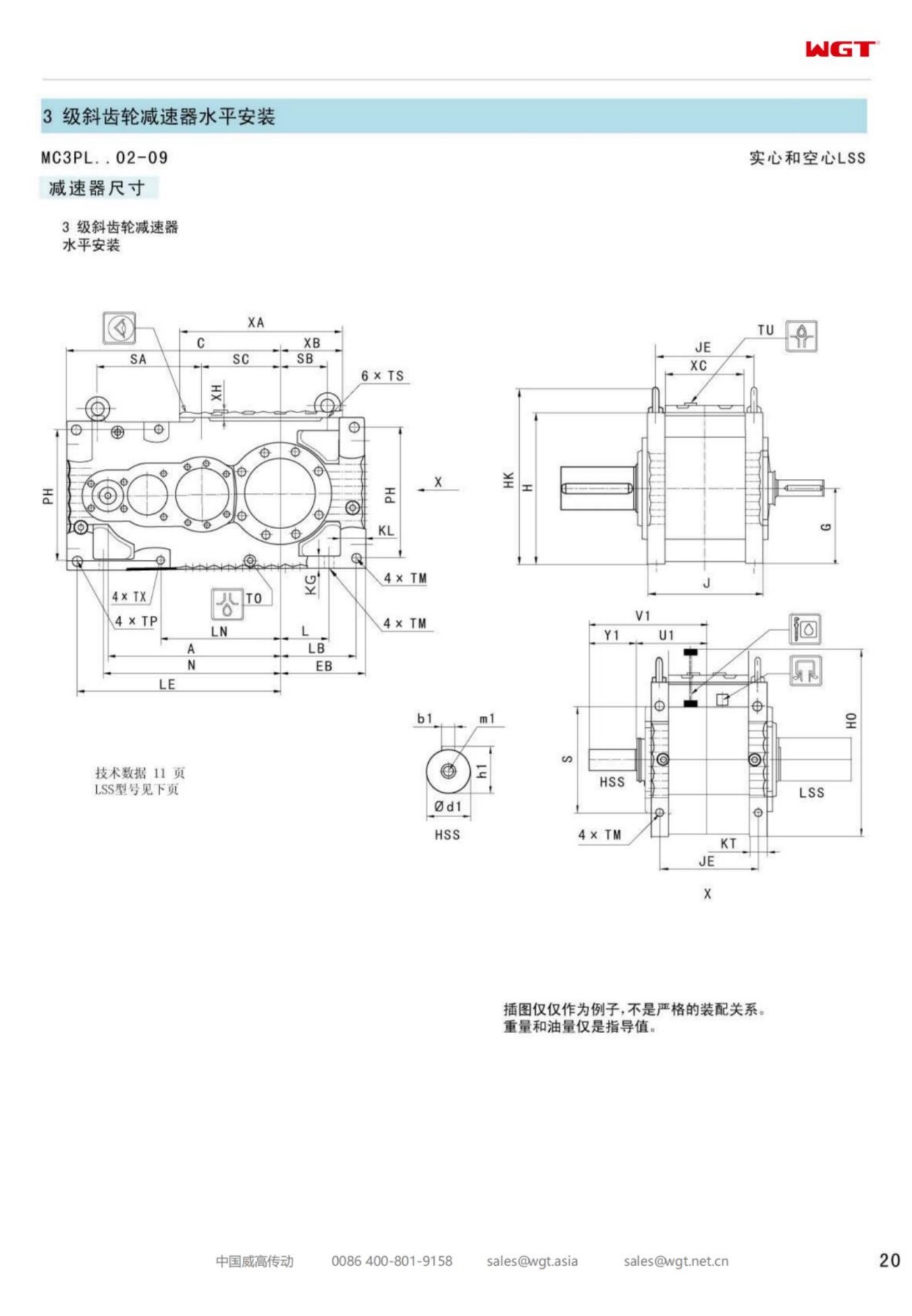
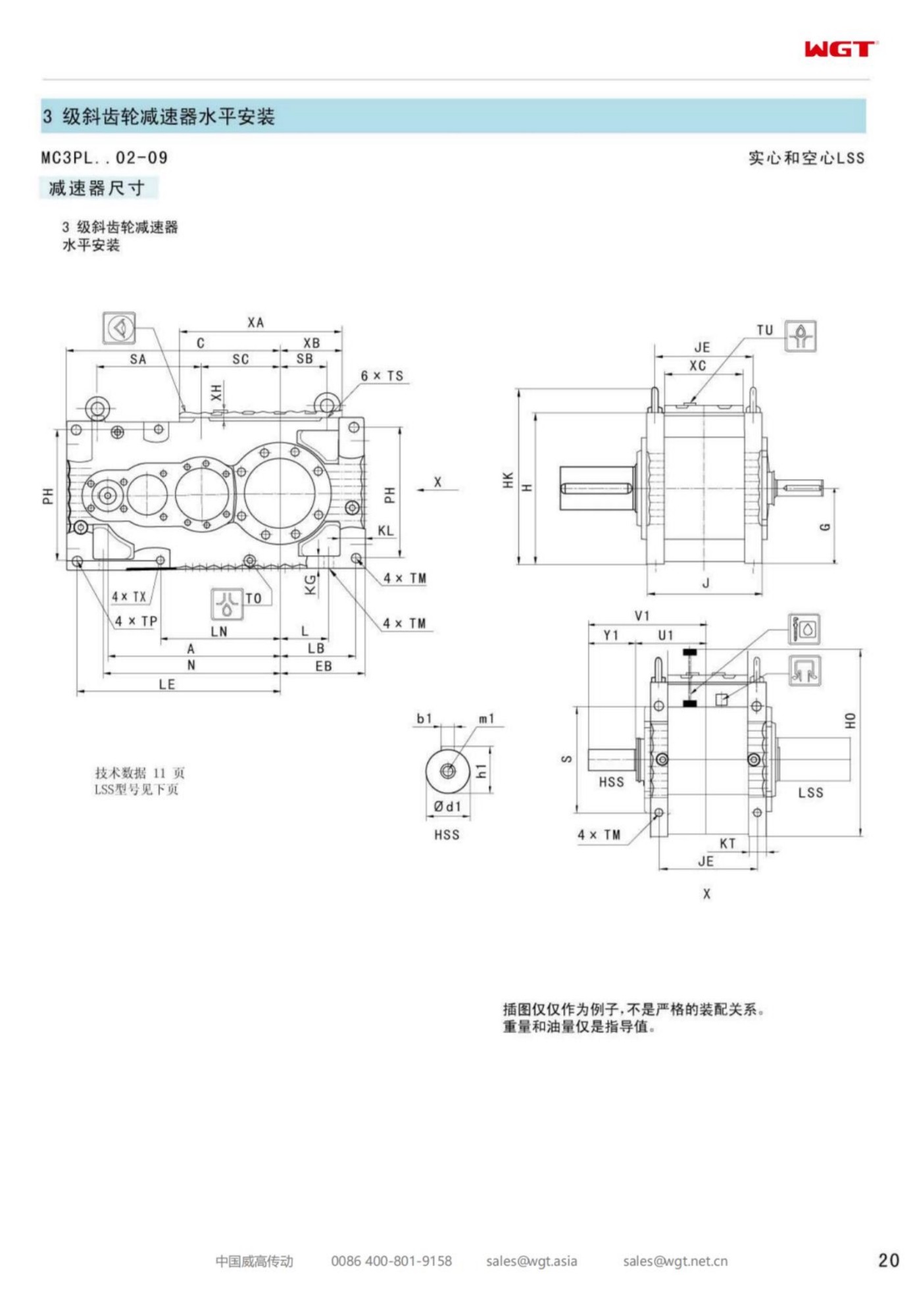
Electrostatic precipitator hoppers collect what the boiler would rather keep in the flue: fly ash that is fine, abrasive, and - once the hopper sprays or a trunk leak adds water - genuinely hostile. The screw conveyor under the hoppers turns that material out continuously, and its drive sits at the tail end doing the least glamorous job in the plant. The MC3PLHF02 three-stage parallel shaft gearbox is built for that seat: a foot-mounted case with a hollow output bore that slips straight over the screw shaft, three helical stages for a deep slow ratio, and no coupling anywhere in the low-speed train.
The notes below walk through what the designation fixes, how a foot-mounted hollow-bore drive behaves on a screw, and what the station should state on the enquiry so the quotation arrives once and correct.
Under the Hoppers, Where the Ash Lands
An ash screw runs because the hoppers must never be allowed to fill. The load is continuous rather than batched, the speed is low, and the torque is dominated by the friction of a screw turning in material that would happily stop it. The drive for that shaft is sized on running torque with a deliberate margin for the moment the ash decides to pack.
Decoding the MC3PLHF02 Designation
Each position in the string is a decision already taken.
| MC | Industrial gear unit family for continuous plant duty |
| 3 | Three reductions inside one case |
| P | Parallel-shaft helical gearing throughout |
| L | Level output axis along the screw line |
| H | Hollow output bore over the screw tail shaft |
| F | Foot mounting on a prepared plinth |
| 02 | Entry frame of the three-stage band |
Read together, the letters describe a drive that bolts down where the screw already runs, hangs itself on the screw shaft through the bore, and needs no coupling, no guard and no alignment job to stay honest.
A Foot-Mounted Hollow Bore Explained
The hollow bore does what a coupling and a pedestal bearing would otherwise do: it carries the screw shaft, holds it concentric with the gearing, and lets the screw maker keep the tail bearing arrangement they prefer. Foot mounting then takes the weight and the reaction into the plinth. The result is a drive that can be removed for internal inspection without disturbing the screw beyond a shaft clamp.
Parallel Stages and a Deep Screw Ratio
Ash screws turn at a fraction of motor speed, and the ratio lands in the deep end of the three-stage band. Splitting that reduction across three meshes keeps each gear set in comfortable geometry and the case at a length the conveyor gallery can actually host - the practical alternative is a two-stage case that is either large or overloaded, and neither suits a basement run.
Wet Ash Is a Different Material
Dry fly ash flows, more or less. Ash with moisture in it packs, bridges at the hopper gate and climbs the screw flights until the drive stalls. The gearbox only sees the torque, but it sees the worst of it: the frame and service factor are chosen for the stall, and the plant side - gate design, flush arrangement, screw pitch - carries the rest.
Mounting Foot Loads and Alignment
Foot mounting transfers real reaction into the plinth, and a plinth that has settled will twist a case that a torque arm would have tolerated. The foundation should be checked flat at installation, the feet shimmed honestly, and the screw shaft allowed to find its own line within the tail bearing clearance. Getting this right once is what keeps the input seal alive.
Starting a Screw That Has Settled
After a shutdown, ash in the trough consolidates, and the first start of the shift asks for several times running torque. Stations that restart empty first - a short jog backward if the screw allows it - spare the drive the worst of it. Where the process will not allow that, the frame is selected against the settled figure, and the extra case metal is the cheapest insurance in the boiler house.
Sealing the Tail End Against Ash Slurry
The output seal faces material that is designed to be abrasive and arrives wet. Seal choice matters more here than anywhere else on the unit: a well-specified lip arrangement with a protected environment will run for years, while an exposed seal in packed ash will not. Discuss the trough's actual behaviour at the enquiry; the answer changes the specification.
Thermal Duty in a Boiler Basement
Basement air is warm and still, and the drive runs continuously. The entry frame of the band carries a small screw comfortably on its own surface area, but the check should be made at the true basement ambient rather than at catalogue room temperature - a five-minute confirmation that removes the only realistic way this duty overheats.
Ratio Arithmetic for the Screw Shaft
Screw speed comes from the ash rate the hoppers must clear, and motor speed is known, so the ratio is arithmetic. Stating both figures on the enquiry - rather than a horsepower and a guess - lets the frame be confirmed against the stall torque the screw will genuinely ask for at restart.
What the Station Enquiry Should Say
The useful enquiry names the screw shaft diameter and keyway, the target screw speed, the motor frame, the ambient the basement really holds, and - because it changes the seals - whether the ash runs wet. A photograph of the plinth and tail arrangement finishes the picture, and the quotation comes back complete.
The HF02 on a Continuous Ash Route
Entry frames exist for the small continuous shafts that keep a plant honest: ash screws, dust valves, small dosing screws. A hollow-bore, foot-mounted three-stage unit at that size is the tidy answer - the drive disappears into the shaft line, and the maintenance list gains nothing it has to think about.
Ash that settles, packs and then has to move - three stages turn through it:
- Fly-ash screw conveyor under ESP hoppers
- Bottom-ash transfer screw at a small stoker boiler
- Dust collection hopper discharge screw at a mill sweep
- Ash conditioning screw ahead of a silo route
- Lime dosing screw on a flue gas treatment line
- Short ash extraction screw feeding a truck load-out
Selection Example: Fly-ash screw conveyor under ESP hoppers
Take an 11 kW motor at 1480 rpm turning the screw shaft at 14 rpm. The ratio follows directly: 1480 / 14 = 105.7, so a ratio near i=106 comes out of the three-stage parallel band, and the frame is confirmed against the stall torque of a screw that has settled overnight, not against the running ash rate. In this case frame two carries the continuous ash route from a foot-mounted case, rides the screw shaft on a hollow bore, and deletes the coupling and guard the tail end would otherwise need. That is the whole calculation. If your duty involves heavy starting, frequent reversing or many stops per hour, tell us and we raise the service factor.
Which Frame Size Do You Need?
| Model | Centre distance | Output | Typical duty |
|---|
| M3PSF50 | size 50 | solid shaft, foot | conveyors, feeders |
| M3PSF60 | size 60 | solid shaft, foot | crushers, mixers |
| M3PSF70 | size 70 | solid shaft, foot | ball mills, shredders |
| M3PSF80 | size 80 | solid shaft, foot | kilns, heavy conveyors |
| M3PSF90 | size 90 | solid shaft, foot | mill and kiln drives |
| M3RSF50 | size 50 | solid shaft, foot, right-angle | inclined conveyors, elevators |
| M3RSF60 | size 60 | solid shaft, foot, right-angle | screw classifiers, feeders |
| M3RHF70 | size 70 | hollow shaft, foot, right-angle | agitators, drum drives |
| M3PHT80 | size 80 | hollow shaft, torque arm, parallel | shaft-mounted conveyors |
| M3RHT90 | size 90 | hollow shaft, torque arm, right-angle | heavy shaft-mounted drives |
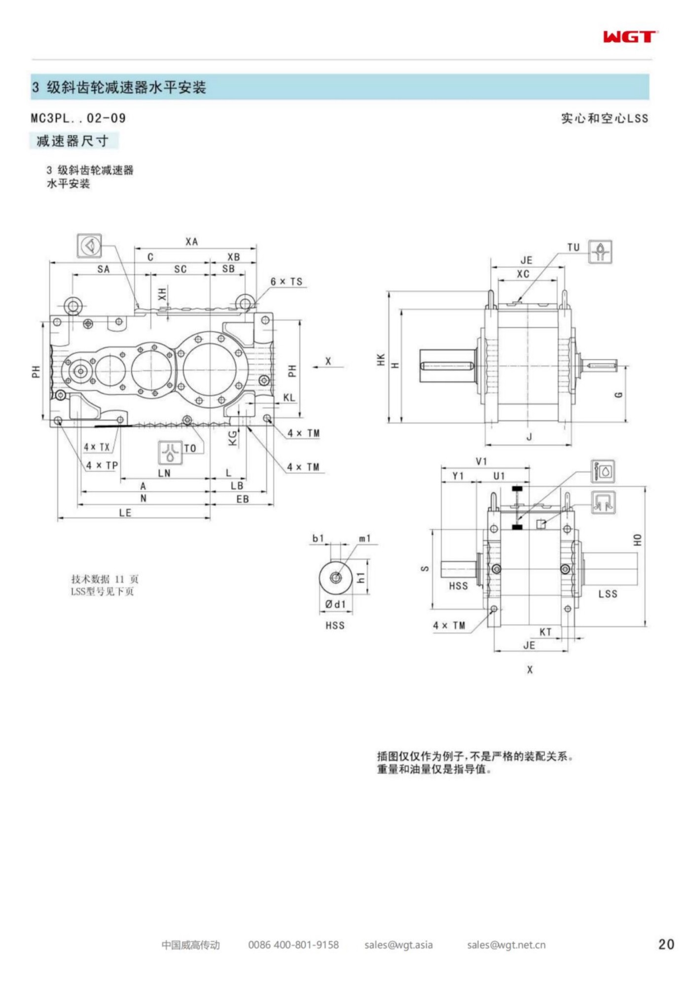
Foot-mounted frames are listed below; torque-arm (T), hollow-shaft (H) and vertical (V) variants are available across the size range. Ask for the outline drawing to check the interface before ordering.
Answers to Common Questions
Should I choose a solid or hollow output shaft?
A solid shaft with a keyed coupling is the flexible, conventional choice. A hollow shaft takes the driven shaft directly with a key or shrink disc, removing one coupling and one alignment step; it is preferred where space or alignment access is limited.
How do I match the gear unit to my existing foundation?
Send the nameplate or the outline drawing of the unit being replaced. Frame dimensions follow the common industry dimension ladder, so foot holes, shaft heights and flange bolt circles normally match without redrilling foundations.
What ratio range does an industrial gear unit cover?
The range spans from low single-digit reductions to very high ratios by combining stage counts: two-stage builds for the lower band and up to five-stage builds for the highest reductions, with intermediate ratios available between catalogue steps on request.
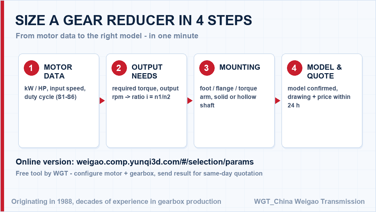
![gearbox sizing steps for engineers]()
Four steps from your application data to a firm model number.
Case Notes from the Field
Stacker-reclaimer travel drive
A bulk terminal drives the travel gear of a stacker-reclaimer with units. Long-travel duty with frequent direction changes is smoothed by the ground gearing, and backlash stays within 20 arcmin over the full rail length.
Automatic parking system
A parking equipment manufacturer uses reducers on its puzzle-type car stackers. The hollow shaft takes the drive axle directly, and the quiet 60-68 dB operation suits installations inside residential buildings.
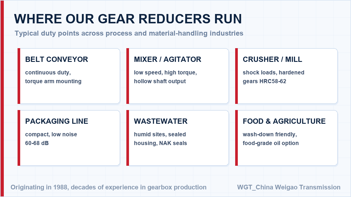
![industrial gear unit application overview]()
A cross-section of the installations we supply every month.
Request the Datasheet and Dimension Drawing
Need documentation for approval? Try the WGT Motor & Gearbox Online Selection System, then send the result sheet - we return a complete datasheet, drawing and price the same day.
We issue complete technical files on request: dimension drawing, rating table, test record format and material certificates, in English and ready for your engineering or purchasing approval package. Looking for a gearbox for wastewater treatment? Tell us the duty point and we will confirm the model in writing.