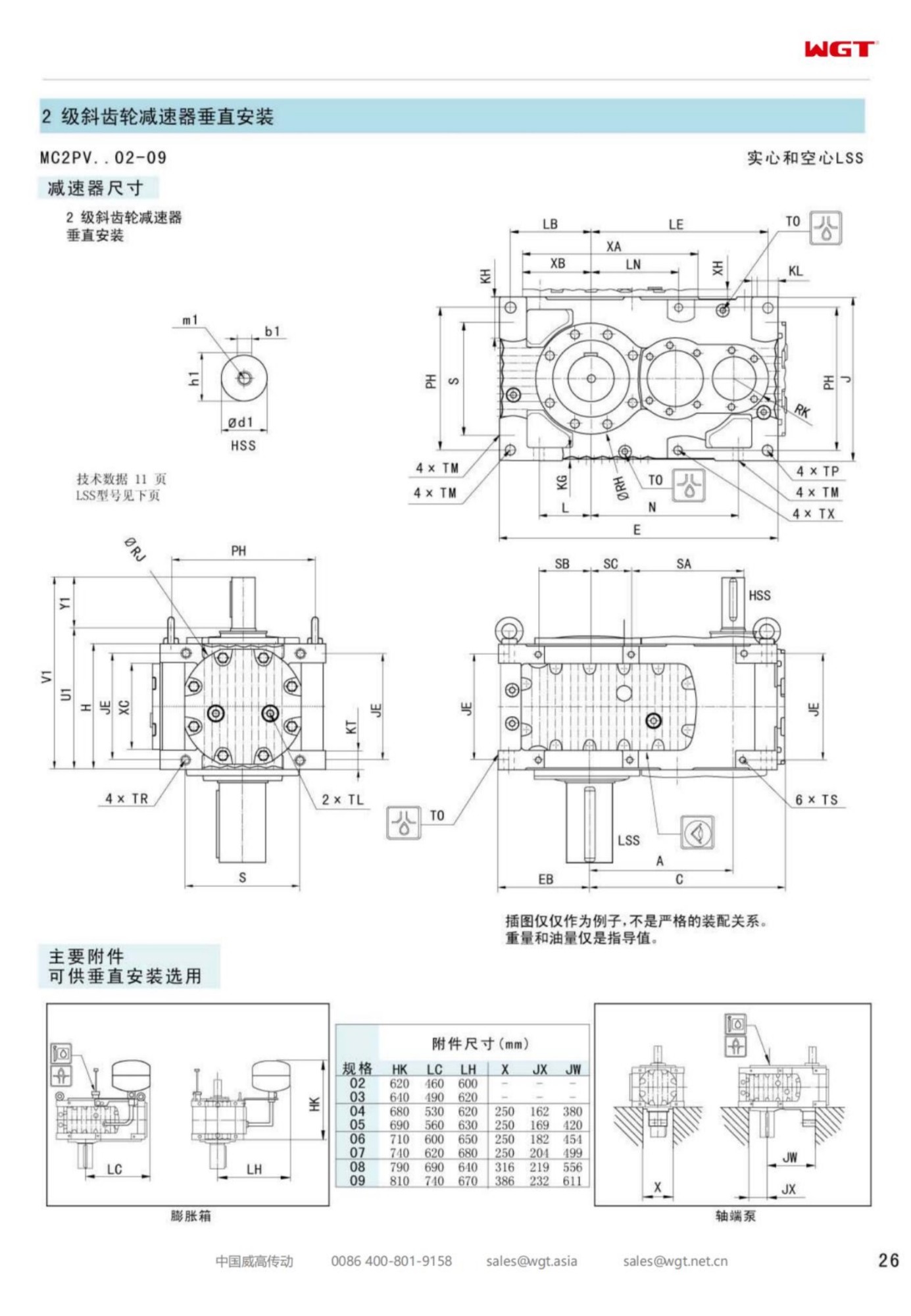
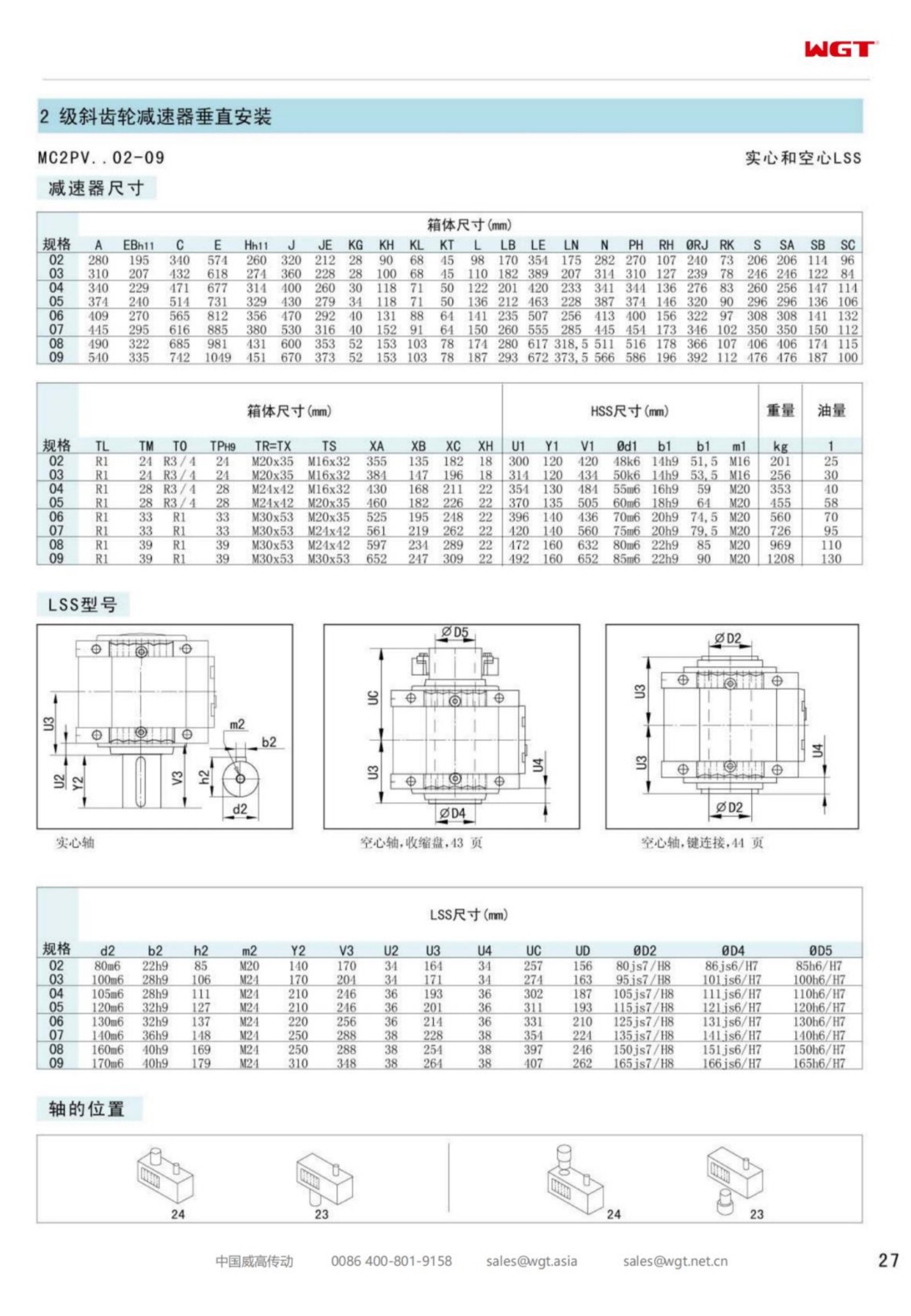
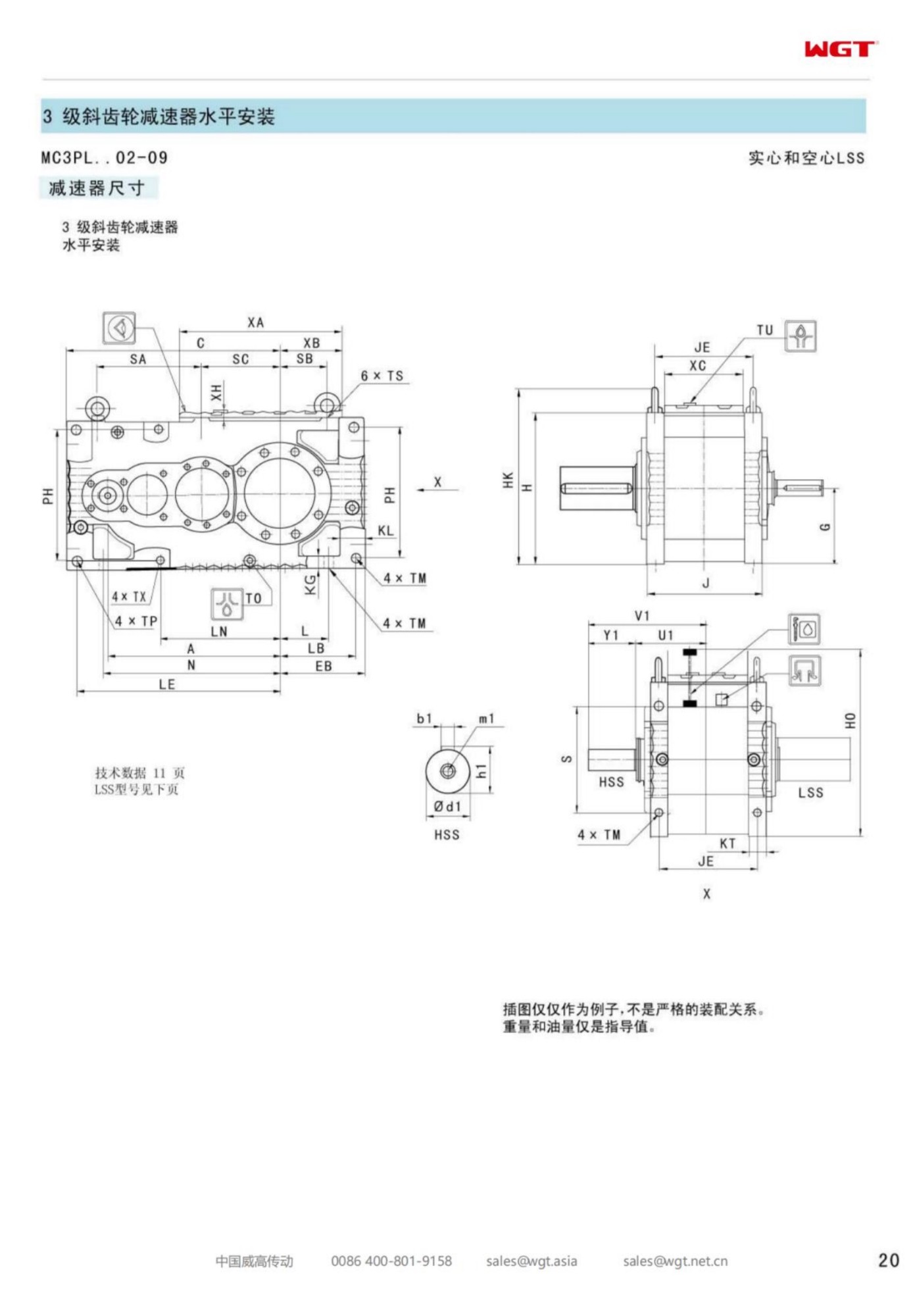
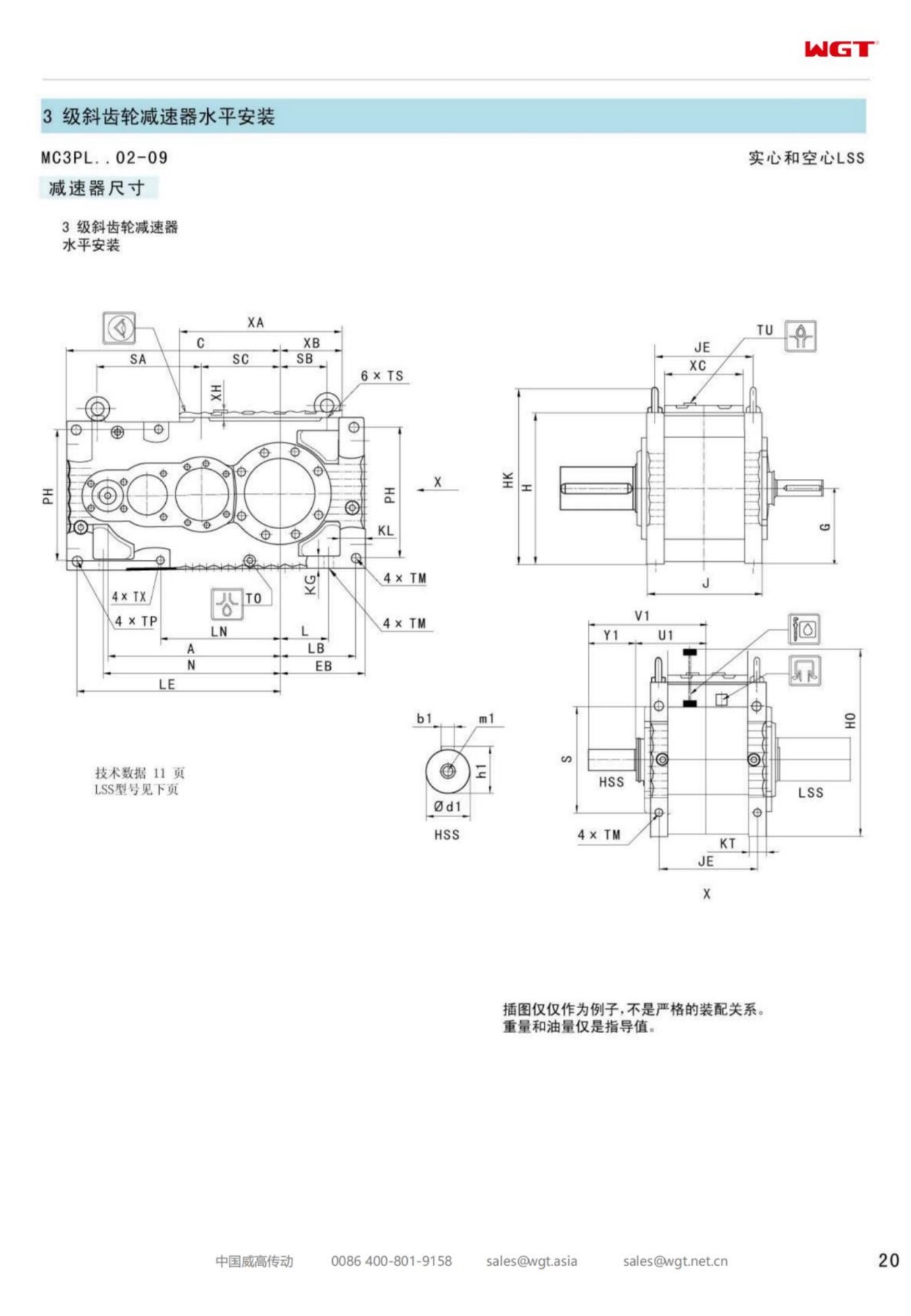
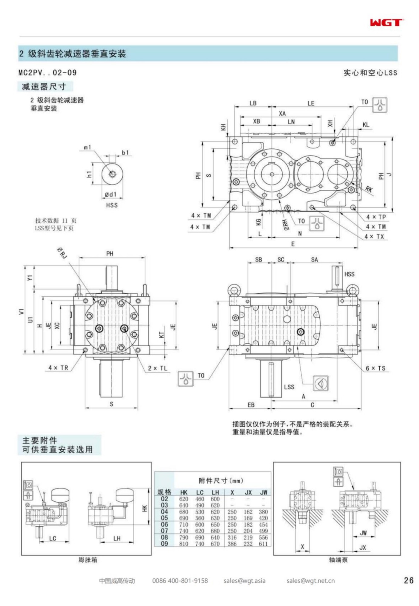
Most gearboxes spend their working life beside the machine they drive, bolted to a plinth with a coupling reaching across. The MC2PVSF02 vertical parallel shaft gearbox turns that arrangement on its head, quite literally: a two-stage helical train in a footed case that sits on a bridge or top plate, with a solid output shaft pointing down into the vessel below. On an agitator, a flocculation paddle or a rake arm, that is the tidy way to build the line - the motor and the gearing stay in the air where they can be watched, and the only thing inside the liquid is the shaft and its seal.
The second frame of the vertical line is the one most tanks meet first. It carries the kitchen-sink duties of a treatment works and the mid-size stirred vessels of a chemicals plant, and it does so with the ordinary virtues of a parallel-shaft train: two meshes, honest efficiency, and a casing whose weight helps rather than hurts when the bridge flexes a little under wind and foot traffic.
When the Drive Sits Over the Vessel
Putting the drive above the process changes the engineering conversation. Gravity now works for the oil instead of against the seals; the gearbox cannot sit in a wash-down puddle or inherit the spillage of the machine below; and every maintenance task - oil check, breather, vibration reading - happens standing on the bridge, not leaning into a sump. The price is that the structure under the case becomes part of the drive system, and a springy bridge will let the whole train nod on every paddle pass unless the plate beneath the feet has been given the stiffness the outline drawing assumes.
Plants that have lived with a bottom-entry or side-entry drive usually need no persuading. The overhead arrangement moves the leaking seal from inside the product to a drip visible from the walkway, turns seal renewal into a half-shift job instead of an entry-permit project, and leaves the tank free of a drive pocket that would otherwise become a settlement trap.
The Type String for a Vertical Frame
The designation decodes with the family's standard table; on this line it is the V that sets the geometry and the S that sets the connection.
| MC | Industrial multi-stage gear unit family |
| C2 | Compact two-stage parallel-shaft series |
| P | Parallel stages in a single horizontal plane |
| V | Vertical build - output shaft pointing down |
| S | Solid output shaft, coupled to the driven machine |
| F | Foot mounting onto a bridge or top plate |
| 02 | Second frame of the vertical line |
The V character is the one that reshapes the internals: bearings, oil galleries and shaft seals are all arranged for a case that spends its life upright over a tank, not flat on a plinth. The S reminds the buyer that this frame connects through a solid shaft and a coupling - the driven machine keeps its own bearing or stub shaft - while the F turns the mounting plate into the civil interface, with bolt pockets and a machined register to centre the unit over the vessel axis.
Solid Shaft in a Vertical Line
A solid output shaft with a coupling is the traditionalist's answer, and on a vertical agitator it is usually the right one. The agitator maker supplies a stub shaft or the gearbox drives the impeller shaft directly through a flanged coupling, and the thrust of the impeller - which on many mixed duties is the largest force in the whole train - is carried by the machine's own thrust bearing rather than fighting the gearbox's oil seals. That division of labour keeps the gearbox simple and lets the shaft be withdrawn for seal work without touching the unit at all.
The coupling deserves respect at installation. A vertical coupling wants its bolts fitted in sequence and torqued evenly, because an unbalanced bolt pattern on a vertical joint shows up as a wobble at the impeller that no amount of run-time will settle. Half a day with a torque wrench at commissioning is the cheapest impeller-balance work the plant will ever buy.
Agitator Duty and the Bending Story
Mixing is not a pure torque job. The paddle or impeller reacts to the liquid with a bending moment, and that moment travels up the shaft into the drive. A vertical parallel-shaft case takes it in the bearings that were designed for it, but the mounting plate takes it too, and the duty class the enquiry declares should include the worst case: start-up over settled slurry, a density excursion in the batch, or the moment a level-sensing failure lets the paddle run half in air. Gearboxes rarely fail on steady mixing; they are ruined by the unsteady day nobody wrote down.
Vibration behaviour tells the story early. A vertical train healthy at commissioning develops a slow climb in the frame-rate component when a bridge has dried out, a bolt has relaxed, or the product has changed. Crews who trend a simple velocity reading on the bridge every month catch these drifts while they are still tightening jobs.
Duties Built Around the Vertical Frame
Vertical frames put the drive over the vessel, not beside it:
- Top-entry agitator drives on a lime slaking tank
- Clarifier rake drives at a municipal water works
- Flocculation paddle drives at a treatment plant
- Mixer drives above a fermenter hall at a brewery
- Stirred-tank drives at a specialty chemicals plant
- Digester agitator drives at a pulp and paper mill
What these duties share is a vessel and a rotating element inside it. Wherever the process wants motion imparted from above, the second frame of the vertical line is the natural drive: enough torque for medium vessels, a footprint small enough for an existing bridge, and the installation habit that keeps the wet end of the machine simple.
Mounting Plate, Bridge and the Quiet Bearing
The interface worth drawing early is the plate under the feet. It wants a machined register to locate the case over the vessel axis, bolt pockets rather than slots, and a thickness that resists the bending moment without a fight. The bridge or top structure beneath it wants bracing that keeps its first natural frequency clear of the paddle pass rate - a structure that rings at the paddle frequency will amplify it, and the crew will blame the gearbox for what the steelwork is doing.
Grouting matters less than on a ground-level plinth but alignment matters more: the unit's axis and the vessel's axis should agree within the coupling maker's figure, taken with the plate clean and the bolts finger-tight before the final torque pass. On a vertical line the alignment is set once, above the tank, and it stays set as long as the plate does.
Sealing a Downward Shaft
Gravity is kind to a downward-pointing seal in one way - oil drains back - and strict in another: anything that drips, drips onto the process. The lip seals on this frame are arranged for vertical service, and the order conversation should name the atmosphere above the liquid: steam from a hot digester, chlorides over a brine tank, dust from a dry blending hall. Each of those picks a seal material and a breather arrangement, and none of them is guesswork.
The habit that protects the seal costs nothing: keep the shaft clean where it passes the seal, wipe it at every inspection round, and never let a scaffold strap or a cable tie ride on the running surface. A scored seal journal on a vertical unit is a shutdown item, not a repair-bench item.
Ratio and Service Factor Above the Liquid
Agitators and rakes live in the middle of the two-stage band: motor speed over impeller speed usually lands between thirty and fifty, exactly where two helical meshes are happiest. The frame is then fixed by torque with the service factor the duty class asks for, and on mixing duty the class is decided by the start - a paddle starting over settled solids asks more of the train than an hour of steady running after it.
Buyers who send the three honest numbers - motor power and speed, target impeller speed, and the worst starting story - get a frame that survives the batch that goes wrong. Buyers who send only the steady running point get a unit sized for the easy day. The difference in price between the two answers is small; the difference in life is measured in years.
Maintenance Without Dismantling the Vessel
The overhead arrangement earns its keep at service time. Oil is checked and changed on the bridge, the breather and seal areas are inspected from a standing position, and the unit can be unbolted and craned clear while the vessel keeps its contents - no pump-down, no confined-space entry, no drive pocket to drain. For works with many tanks, a spare frame in the stores turns a gearbox question into a half-day swap.
The one job that must not be improvised is coupling separation: the draw bolts come out, the shaft is supported before the last bolt is slackened, and nobody lets an impeller shaft hang on the seal while lunch is taken. A note in the maintenance file saying so is worth more than any instruction book.
What a Vertical Enquiry Needs
The enquiry that closes in one pass for this frame reads plainly: vessel and driven element with impeller or paddle type; motor power, speed and starting method; output speed and the tolerance the process accepts; the bending moment or the shaft drawing, if the machine maker has one; hours per day and batch pattern; the atmosphere above the liquid - steam, salt, dust - because the seals live there; and the mounting plate drawing or at least its thickness and bolt positions.
With those lines filled, the reply is a firm quotation and a plate drilling the fabricator can work from, and the drive goes in during the tank's planned stop rather than causing one. The second vertical frame is ordinary machinery in the best sense: two meshes, a solid shaft, and a job it has done above tanks for decades.
Questions We Hear Most Often
How often should the oil be changed in heavy duty?
With mineral oil, plan an initial change after the running-in period and then roughly every 5,000 hours. Synthetic oil stretches the interval to around 10,000 hours. Hot environments, dust or frequent starts shorten the interval - we advise the schedule with the quotation.
Can the unit be rebuilt instead of replaced?
Yes. Bearings, seals and gear sets are available as spare internals, and the horizontally split housing allows inspection and reassembly on site. Many operators overhaul units during annual shutdowns instead of buying new.
What ambient and altitude limits apply?
The standard build suits -10 to +40 degrees C at altitudes below 1,000 m with the supplied oil grade. Colder sites get synthetic oil and heaters; high altitudes or hot climates may call for the next frame size or forced cooling.
Choosing the Right Frame Size
| Model | Centre distance | Output | Typical duty |
|---|
| M3PSF50 | size 50 | solid shaft, foot | conveyors, feeders |
| M3PSF60 | size 60 | solid shaft, foot | crushers, mixers |
| M3PSF70 | size 70 | solid shaft, foot | ball mills, shredders |
| M3PSF80 | size 80 | solid shaft, foot | kilns, heavy conveyors |
| M3PSF90 | size 90 | solid shaft, foot | mill and kiln drives |
| M3RSF50 | size 50 | solid shaft, foot, right-angle | inclined conveyors, elevators |
| M3RSF60 | size 60 | solid shaft, foot, right-angle | screw classifiers, feeders |
| M3RHF70 | size 70 | hollow shaft, foot, right-angle | agitators, drum drives |
| M3PHT80 | size 80 | hollow shaft, torque arm, parallel | shaft-mounted conveyors |
| M3RHT90 | size 90 | hollow shaft, torque arm, right-angle | heavy shaft-mounted drives |
One family, two layouts. Choose P for a coaxial-in / parallel-out drive train, R when the motor must turn 90 degrees; then pick the shaft type and mounting style that the machine interface needs.
Selection Example: Top-entry agitator drive on a lime slaking tank
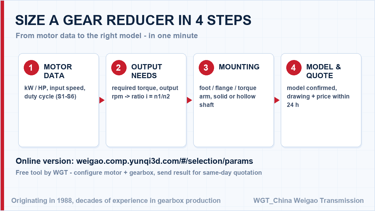
Take an 11 kW motor at 1460 rpm turning the agitator at 34 rpm. The ratio follows directly: 1460 / 34 = 42.9, so a ratio near i=43 is drawn from the two-stage band, and the frame is checked against the heavy start when the paddle switches on over settled slurry after a maintenance stop. In this case the vertical frame hangs over the tank edge on its footed top plate, and the solid output shaft carries the agitator through a split coupling that can be opened for seal service without touching the unit. It always comes down to those three figures. Send them over and we confirm the frame, ratio and service factor in writing.
![online gearbox selection system workflow]()
Selection workflow used by our engineers for every quotation.
Real-World Duty Points
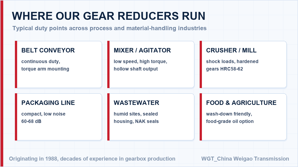
Lime kiln auxiliary drive
A lime producer fits a smaller industrial gear unit as the auxiliary drive of its rotary kiln. Turning the kiln slowly during shutdowns and start-ups is exactly the low-speed, high-torque duty the frame was chosen for.
Tunnel boring backup drive
A tunnelling contractor uses industrial gear units on the backup gantry conveyors of its TBM. The units arrived dimensionally matched to the gantry interfaces, so installation took hours rather than days.
![right angle gearbox duty points overview]()
An overview of the duty points this series is built for.
Torque Margin Checked Before Every Quotation
No catalogue guessing. Use the WGT Motor & Gearbox Online Selection System to turn your motor data into a model number, and we will quote that exact unit within the day.
Every quotation includes the calculated service factor and the resulting torque margin, so the unit you buy covers the real duty - including starts, jams and reversals - not just the average load. Looking for a gearbox for steel mill? Tell us the duty point and we will confirm the model in writing.