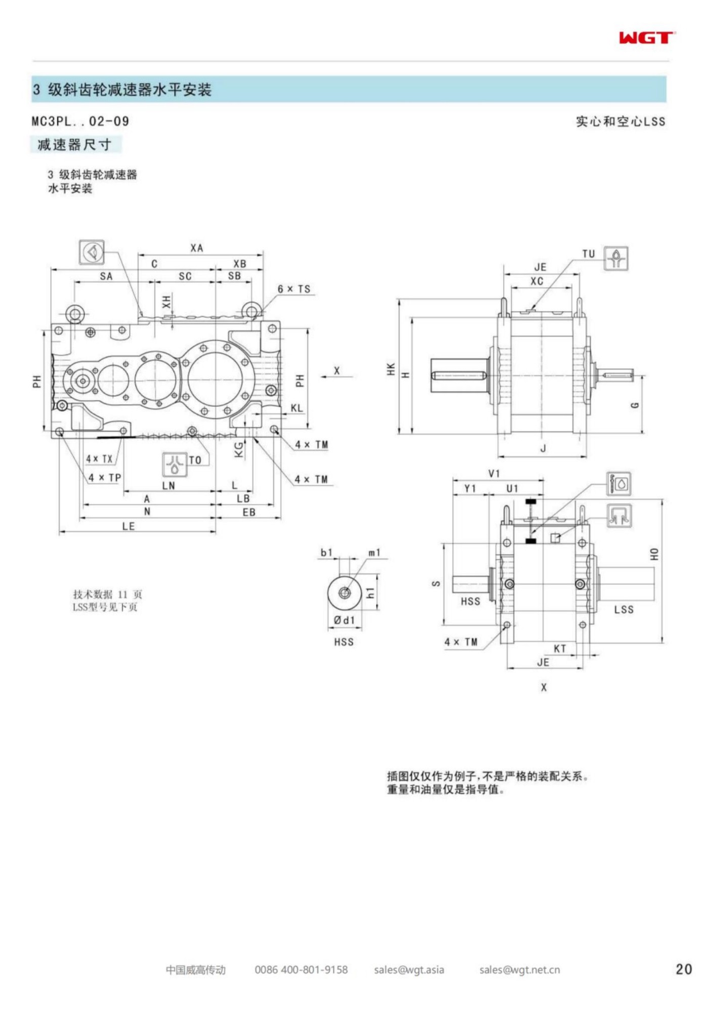
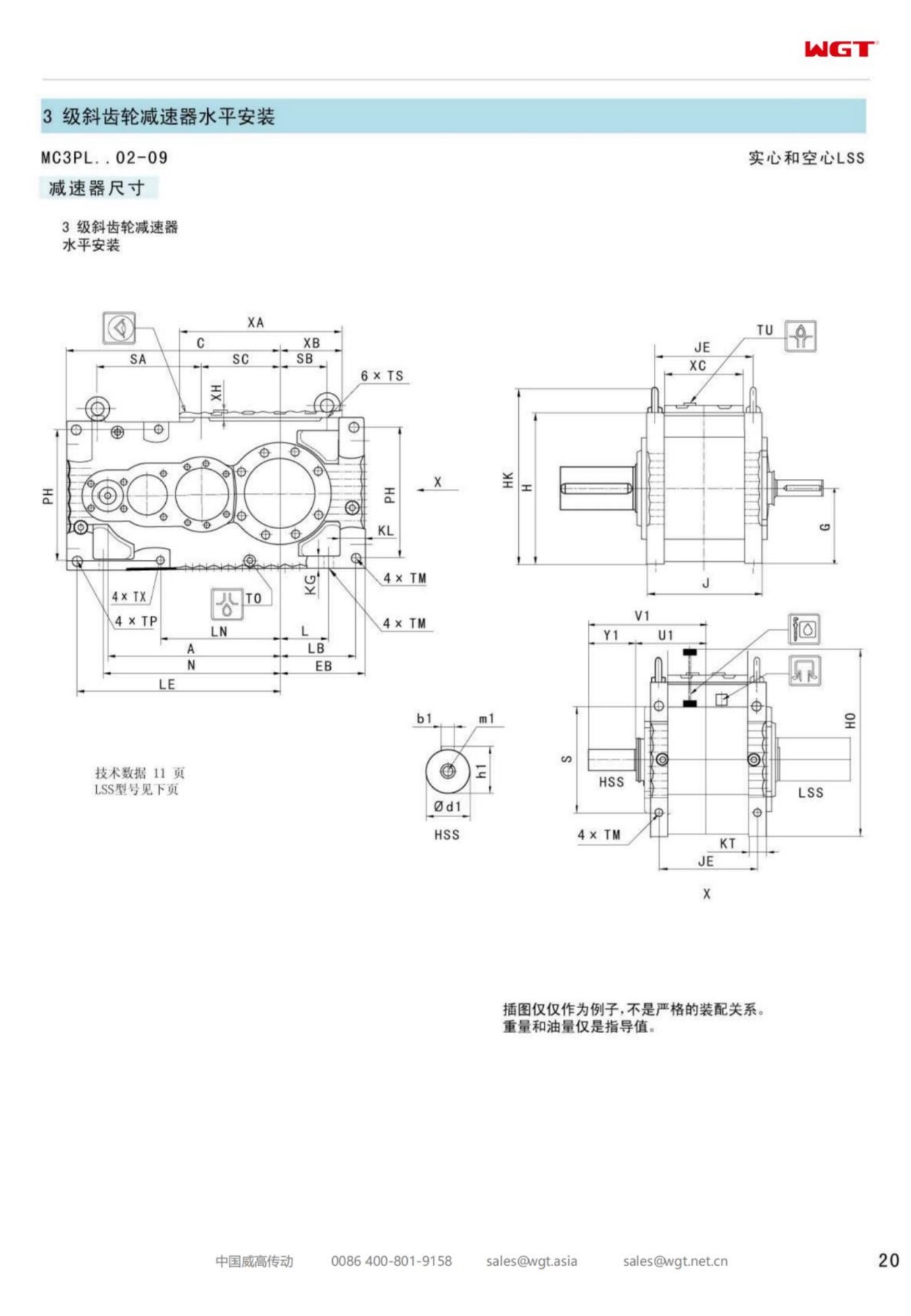
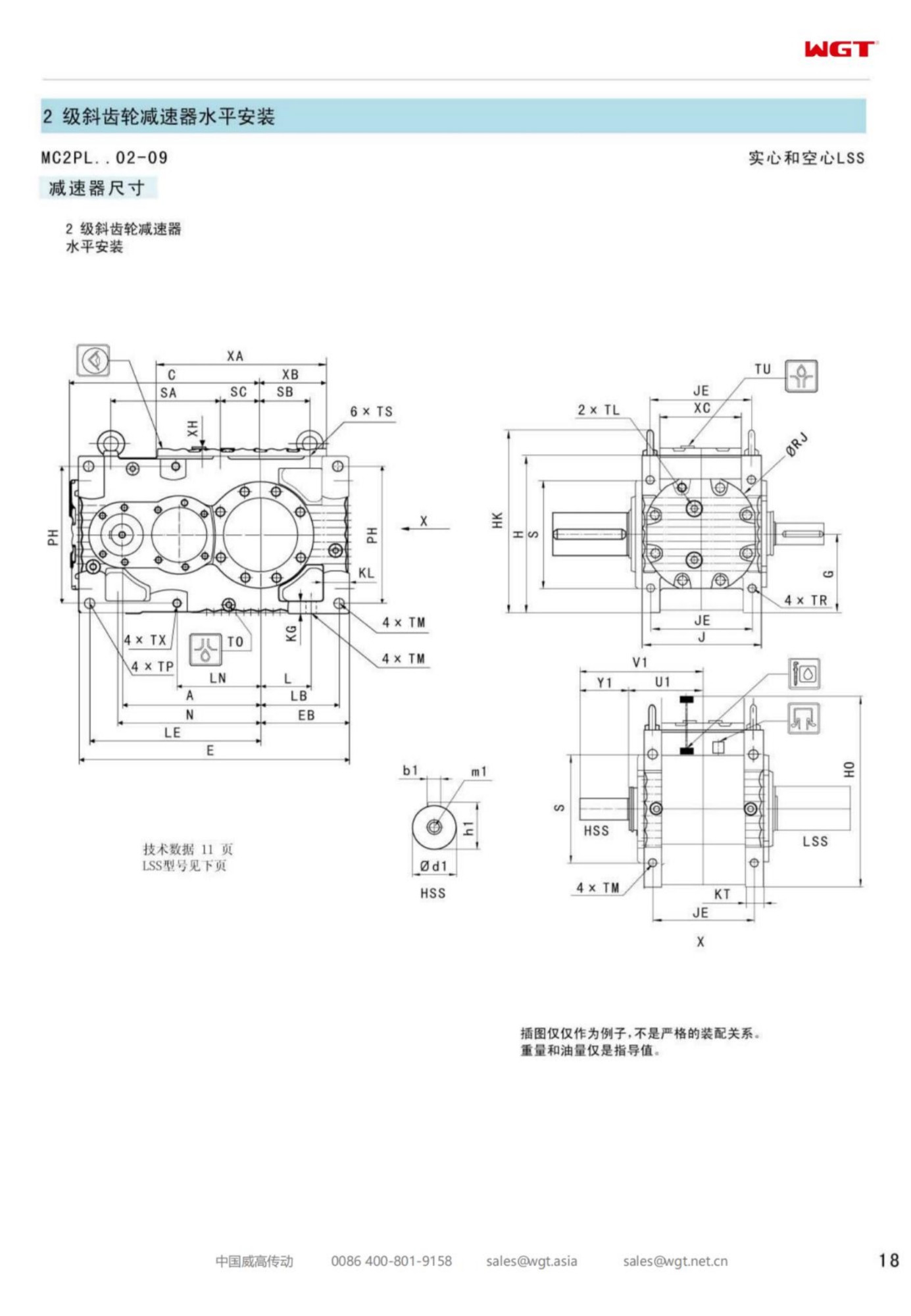
Sooner or later a plant builds a conveyor that one gearcase cannot sensibly drive. The belt gets long, the tonnage climbs, or the head station is asked to move a load that would need a case so large it could not be handled in the tower. The answer is almost always two units working the same line, and the MC2PLST05 torque arm gearbox is the frame in this band that exists for that arrangement: mid-band torque, a solid output shaft, and a torque arm that lets each case hang on structure instead of demanding a bedplate the tower does not have room for.
Two drives on one line is not twice one drive. Every question the single-unit installation answers quietly becomes a decision: which unit takes which share of the load, what happens on a start when both motors pull at once, how the line is braked when there are two inertias instead of one, and what the alignment targets mean when the coupling train runs between two machines that can each move independently. None of these is exotic, and all of them are cheaper to settle on paper than on a tower at three in the morning.
Frame Five: When the Drive Line Gets Longer
Frame five is where the family's step pattern meets a different kind of duty. Frames two through four mostly serve single machines with single motors; the fifth step is where plants start pairing units, and where the frame's margin is spent on coordination rather than on raw torque. The case itself is a level two-stage build with a solid output shaft and an arm, exactly as its smaller siblings, and its selection is argued the same way - running torque, starting peaks, hours, ambient - with one addition: the duty now includes another gearcase, and that changes the worst case.
The worst case on a paired line is rarely the steady load. It is the moment one unit carries more than its share - a motor that comes up slightly earlier, a coupling that grips a little tighter, a belt that loads unevenly across its width - and does so for long enough that the imbalance becomes a thermal fact rather than a transient. A frame chosen with margin for that condition behaves like a frame chosen for a single drive; one chosen on the sum of the two running torques behaves like a frame that is being asked a question it was never designed to answer.
Decoding MC2PLST05
The string follows the family grammar; the final pair of digits places the frame inside the band.
| MC | Industrial gear unit family for continuous plant service |
| 2 | Two helical stages in a single level case |
| P | Parallel-shaft layout, input and output parallel |
| L | Level build, both shafts horizontal |
| S | Solid output shaft through a conventional coupling |
| T | Torque arm reaction into structure, no foundation |
| 05 | Fifth frame: the step where two units share one line and the duty becomes a coordination problem |
As an ordering document the string fixes geometry and nothing else. Each of the two units in a paired installation needs its own complete specification - ratio, service factor, coupling, bracket, brake or backstop, lubrication - and the pair needs a third document that describes the line: belt speed, tonnage, the driven shaft's arrangement, and how the two units are intended to share the work. That third document is the one plants forget to write, and it is the one that decides whether the pair behaves as a system or as two machines that happen to be bolted to the same conveyor.
Tandem and Dual-Drive Layouts
Two units on one conveyor can be arranged in a handful of ways, and the arrangement decides most of what follows. At one end of the range, both units drive the same head shaft from opposite sides or from the same side through a common shaft extension, which is compact and keeps the coupling trains short. At the other, one unit drives the head pulley and a second drives a pulley further down the belt, which shortens the belt's tension path and lets each case sit where there is room. In between sit layouts where a single shaft carries two cases in series, and each of these has its own alignment and load-sharing behaviour.
The choice is usually made by the conveyor designer rather than the gearbox supplier, and it is made early, because it fixes the tower steel. What the gearbox side needs from that decision is modest but specific: the distance between the two mounting positions, whether the driven shaft is common or separate, the direction each arm must react against, and the space each case needs for its coupling and guard. Given those, the two frames can be specified as a matched pair rather than as two orders that happened to be placed in the same month.
Peak Torque From Shared Starts
A start is the only moment on a conveyor when the gearcases see torque they were not sized for by the running calculation. The belt and its load are at rest, the motor delivers locked-rotor torque for as long as it takes to break the belt away, and the gearset absorbs whatever the coupling passes through. On a paired line the two units do not necessarily break away together, so one case can carry the whole line's breakaway load for a fraction of a second and a significant share of it for the next several seconds.
That is the condition the service factor has to cover, and it is why the enquiry should state how the line is started. Direct-on-line starting with both motors energised together is a different world from a soft starter or a drive that ramps the pair up over twenty seconds; a loaded restart after a trip is different again, because the belt may be sitting on product. Where the plant can start one unit slightly ahead of the other, the peak on the second unit falls noticeably, and where it cannot, the frames are simply specified with the peak in view. Either way the information belongs in the order rather than in the assumption.
Structure Stiffness Behind the Bracket
An arm-mounted case transfers its reaction into whatever the bracket is bolted to, and on a paired installation two cases transfer two reactions into the same tower. The steel that was adequate for one drive may flex measurably under two, and flex in the bracket's support is indistinguishable at the coupling from misalignment. This is the single most common source of trouble on multi-drive installations that were otherwise specified correctly: nothing failed, the structure simply moved more than the alignment targets allowed for.
The answer is a conversation with whoever owns the steel, held before the brackets are detailed. Ask what deflection the tower is expected to see under belt pull at full load, and whether the two brackets land on the same member or on two that move relative to each other. Where the answer is uncomfortable, the brackets can be tied together, moved to stiffer steel, or the alignment targets loosened with a coupling that tolerates more misalignment. All three are drawing-board fixes. The site version of the same problem involves a crane, a welder and a production stoppage.
Alignment Across a Two-Machine Line
Single-drive alignment is a closed problem: set the case, check the coupling, record the numbers. A paired line adds a second reference and a third, because the two gearcases are aligned to the machine and also to each other through the belt. A common driven shaft makes this easier - both cases reference one shaft, and the targets are the coupling makers' figures at each end. Separate pulleys make it harder, because each case can be perfectly aligned to its own pulley while the belt runs with an edge load that neither case can see.
The discipline that works is to align each unit to its own machine first, record it, then check belt tracking under load and treat any correction as a structural adjustment rather than as a coupling shim. Re-checking after the first weeks matters more here than on a single drive, because the tower is settling under a load it has not carried before. Numbers on file from commissioning are what turn that settling into a measurement instead of a suspicion.
Braking a Line With More Than One Inertia
An inclined conveyor with two drive units has two sources of stored energy and two places to put a brake. The usual arrangement is a disc on one coupling with a caliper sized for the whole line, which is simple and puts the brake where hands can reach it; the alternative is a brake on each unit, which halves the torque per caliper and adds a synchronisation question, since two calipers that engage a fraction of a second apart apply their load unevenly through the belt.
Whichever is chosen, the gearcases see the brake as a reaction through their output shafts, and the frame that carries the disc carries the larger share of that reaction. That is a reason to put the brake on the unit with the greater reserve rather than on the one that happens to have space. It is also a reason to state holding torque, stopping time and the number of stops per shift in the enquiry, because a brake sized for an emergency stop and one sized for every shift stop are different components living in the same housing.
Load Sharing Between Two Units
Perfect load sharing between two drives on one belt does not exist, and the useful question is how much imbalance the installation should be expected to absorb. Two identical motors fed from the same supply will still differ slightly in slip; two identical gearcases will differ in backlash and in the stiffness of their brackets; the belt itself distributes tension unevenly across its width. The result is a steady-state imbalance that is normal, plus a transient one at every start that is larger and shorter.
The practical response is to specify both frames for the duty's total load with a service factor that acknowledges imbalance, rather than for half the load each, and then to verify the assumption once the line is running. Motor current on both units at full load is the cheapest measurement available and it tells the plant whether the pair is behaving as intended. Where the imbalance is persistent and large, the cause is usually structural or a coupling that is not gripping evenly, and it is worth finding rather than absorbing with a larger frame.
Condition Monitoring on a Paired Installation
Two units give the plant something a single drive never can: a reference. When one case runs warmer than the other under the same load, or vibrates differently, the difference is information that does not need a historic baseline to be meaningful. Plants that run paired drives well tend to build their monitoring around exactly that comparison - oil temperature, bearing temperature and vibration read as a pair, at the same load and the same ambient.
The routine is modest. Note both temperatures on the same schedule and at comparable loads; sample both oils at the same interval, since comparing samples taken months apart tells you nothing; and take one vibration reading per case at a fixed point. After a few months the pair establishes its own normal, and a divergence shows up long before either unit reaches a limit. On a line the plant depends on, that early warning is the whole value of having two units rather than one large one.
Duties That Belong on Frame Five
Lines driven by two units, where the installation has to be specified as a system:
- Twin-drive head station of an overland conveyor at an iron ore mine
- Paired boom conveyor drives on a stacker-reclaimer at a coal terminal
- Two-unit kiln feed belt drive at a lime plant
- Dual boom conveyor drive on a ship loader at a fertiliser terminal
- Two gear units on a long apron conveyor at a copper smelter
- Tandem drive on the raw mill reject conveyor at a cement works
What these positions share is a line that outgrew a single drive, and a head station where the structure had to accept two reactions instead of one. Frame five's value in those duties is not only torque: it is a case small enough to hang where there is room, with an arm that puts the reaction into steel rather than into a foundation nobody can pour.
Spares Strategy for a Paired Drive
A plant with two identical units has an option a plant with one does not: it can treat the pair as a small fleet. Consumables - coupling elements, seals, breathers, arm bushings - are worth holding in pairs, because they are cheap and because a failure on one unit should not wait on a purchase order while the line stands. A complete spare gearcase rarely makes sense at this size; the exchange lead time is usually shorter than the interval between overhauls on a well-run drive.
What does make sense is documentation held twice: coupling drawings with element part numbers, seal and bearing references, tightening figures for the arm and bracket hardware, and the alignment records from commissioning. On a paired installation the records matter more than the spares, because the second unit's behaviour is only interpretable against the first's. A plant that kept the paperwork can diagnose a divergence in an afternoon; one that did not is reduced to comparing two unknowns.
The Enquiry for a Multi-Drive Duty
The enquiry for a paired line is a single document describing a system. It lists belt width, length, incline, tonnage and belt speed; the motor or motors with their starting method; the arrangement - common shaft, separate pulleys, or cases in series - and the distance between mounting positions; the hours, ambient and dust conditions; the brake or backstop requirement and where the plant wants it; and the shaft measurements and available gaps at each end. A sketch of the head station completes it.
Sent that way, the answer comes back as two matched selections and a note on how they are expected to share the load, which is the document a maintenance planner can actually work from. Sent as two separate kilowatt enquiries, the answer is two prices and a set of assumptions that will be tested on the tower. Frames of this size have carried paired duties for decades; the ones that do it quietly were specified as a system, and the ones that generate service calls were usually specified twice.
Model Range and Centre Distances
| Model | Centre distance | Output | Typical duty |
|---|
| M3PSF50 | size 50 | solid shaft, foot | conveyors, feeders |
| M3PSF60 | size 60 | solid shaft, foot | crushers, mixers |
| M3PSF70 | size 70 | solid shaft, foot | ball mills, shredders |
| M3PSF80 | size 80 | solid shaft, foot | kilns, heavy conveyors |
| M3PSF90 | size 90 | solid shaft, foot | mill and kiln drives |
| M3RSF50 | size 50 | solid shaft, foot, right-angle | inclined conveyors, elevators |
| M3RSF60 | size 60 | solid shaft, foot, right-angle | screw classifiers, feeders |
| M3RHF70 | size 70 | hollow shaft, foot, right-angle | agitators, drum drives |
| M3PHT80 | size 80 | hollow shaft, torque arm, parallel | shaft-mounted conveyors |
| M3RHT90 | size 90 | hollow shaft, torque arm, right-angle | heavy shaft-mounted drives |
Frame sizes in this series follow a widely used industrial dimension ladder: foundations, couplings and guards of the existing installation are reused as they are.
Proven Installations
Lime kiln auxiliary drive
A lime producer fits a smaller industrial gear unit as the auxiliary drive of its rotary kiln. Turning the kiln slowly during shutdowns and start-ups is exactly the low-speed, high-torque duty the frame was chosen for.
Tunnel boring backup drive
A tunnelling contractor uses industrial gear units on the backup gantry conveyors of its TBM. The units arrived dimensionally matched to the gantry interfaces, so installation took hours rather than days.
![gearbox applications in quarry food and water plants]()
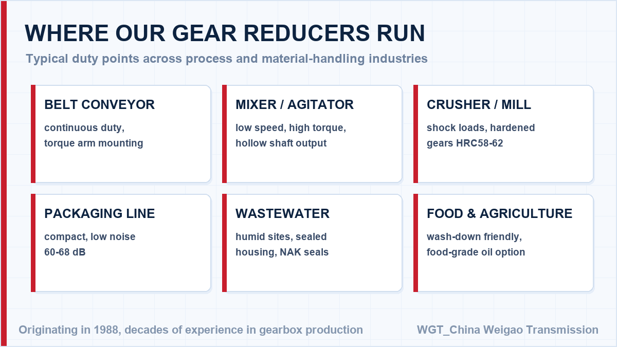
Conveyor, mixer, crusher and wastewater duties share the same gear family.
Selection Example: Twin-drive head station of an overland conveyor at an iron ore mine
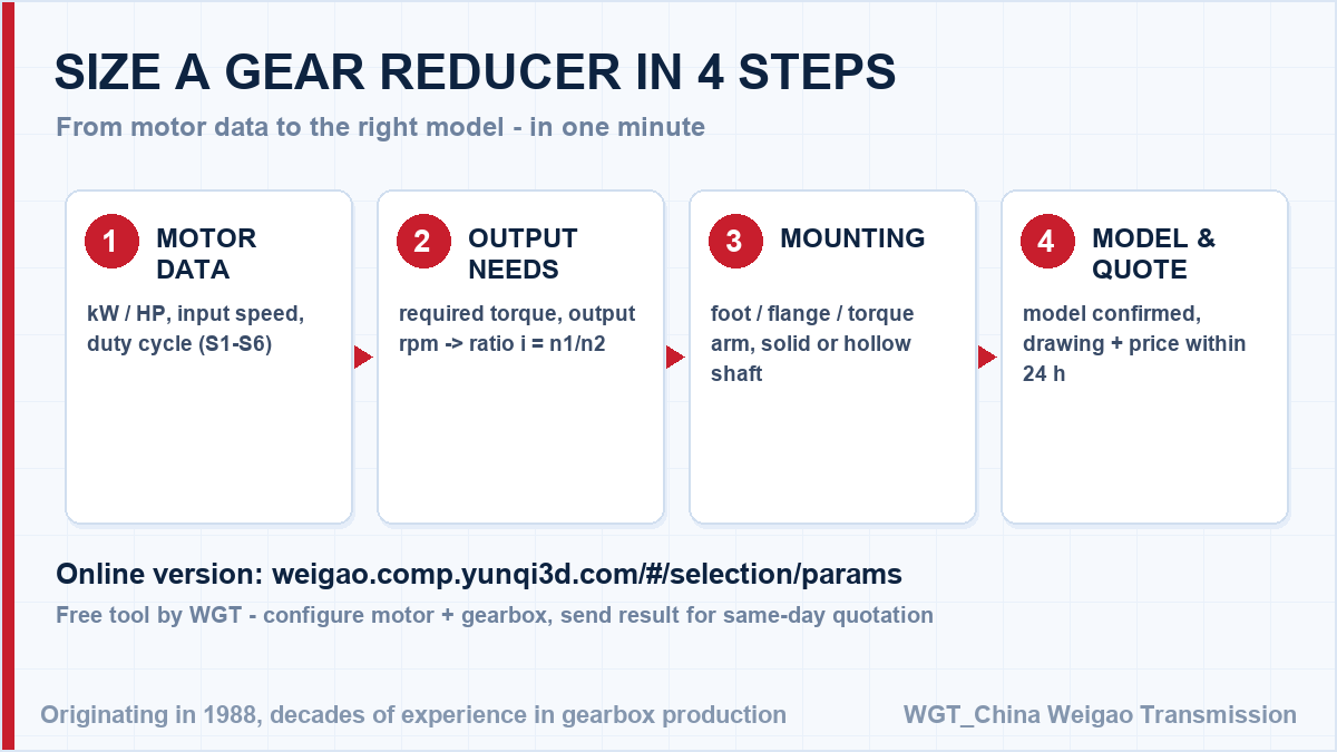
Take two 75 kW motors at 1490 rpm turning a common head shaft at 38 rpm. The ratio follows directly: 1490 / 38 = 39.2, so a ratio near i=39 is selected for each unit, and both frames are checked against the breakaway peak the pair delivers when the loaded belt is restarted. In this case frame five carries its share of the shared start with margin, and two arm-mounted cases hang where the tower has room instead of demanding one very large foundation. Motor speed over target speed gives the ratio; the driven machine decides the service factor, and the two together decide the model.
![industrial gear unit sizing procedure diagram]()
The four inputs the online selector asks for.
Engineering Support Before You Buy
Unsure about the frame size? Work out the ratio, torque and frame size yourself with the WGT Motor & Gearbox Online Selection System, then send the result - we confirm it in writing.
Our selection engineers check every enquiry against the rating tables, including shock class and daily running hours. You get the calculation, not just a part number - at no charge and with no obligation. Looking for a gear reducer for screw conveyor? Tell us the duty point and we will confirm the model in writing.
FAQ: Selection, Mounting and Maintenance
How is the unit transported and lifted on site?
Units ship in export wooden crates with lifting points on the housing clearly marked. On site, lift only from these points with the specified slings - lifting from shafts or covers is expressly forbidden in the manual.
What tooth quality and grinding finish do you apply?
Gearing is case-hardened and profile-ground to international accuracy grades, with crowning and end relief applied to avoid edge loading. This is what keeps noise and vibration stable over years of continuous duty.