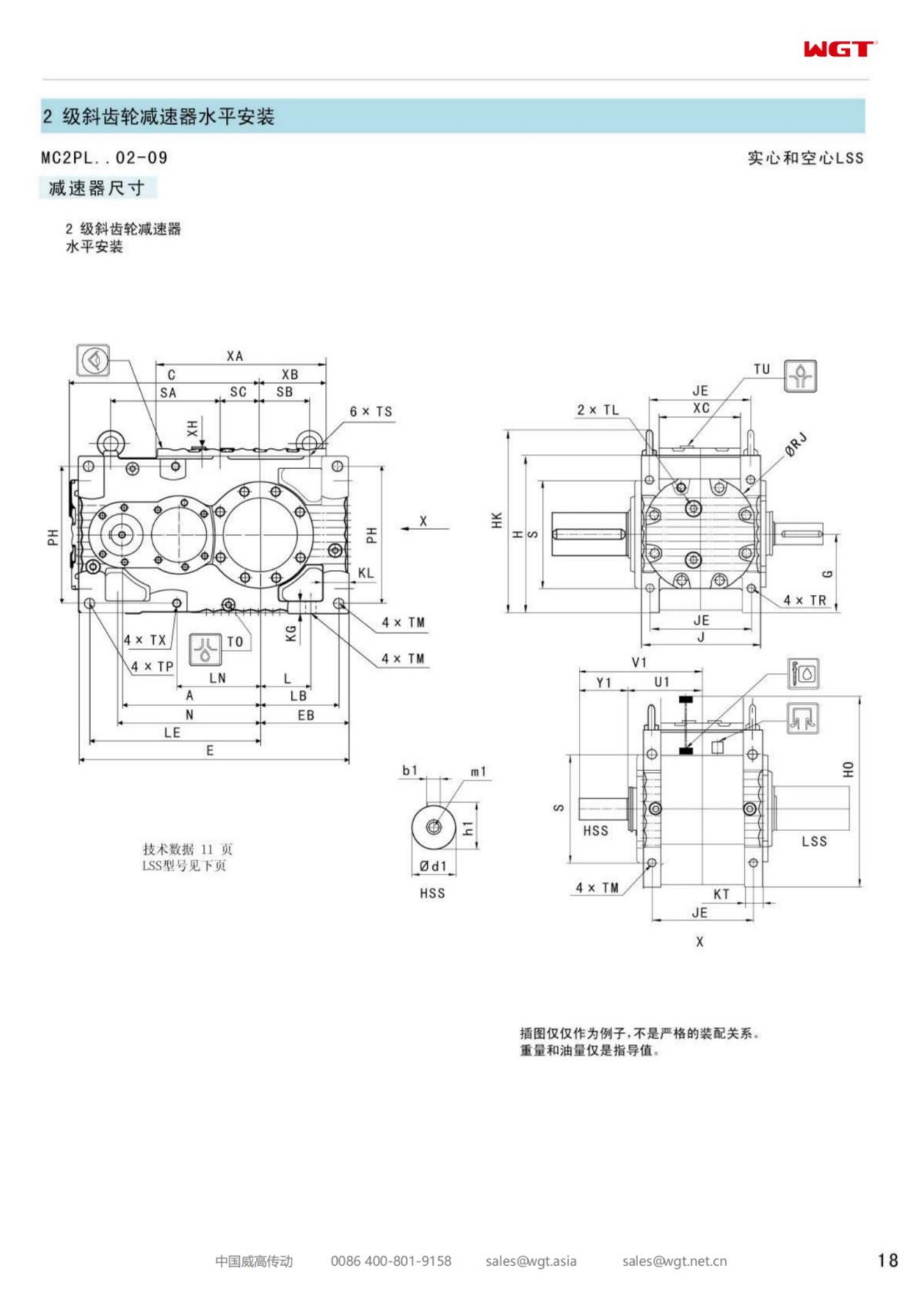
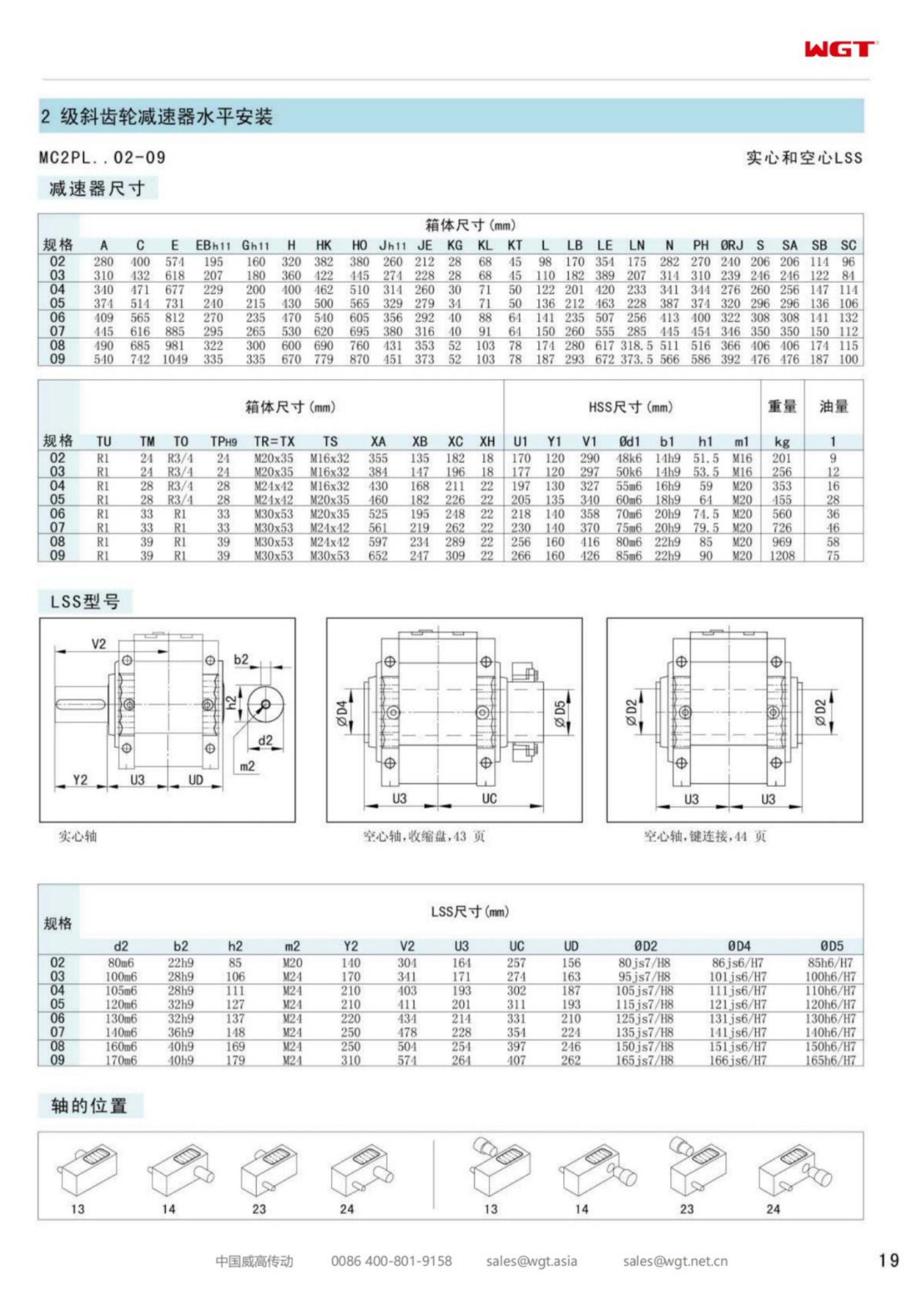
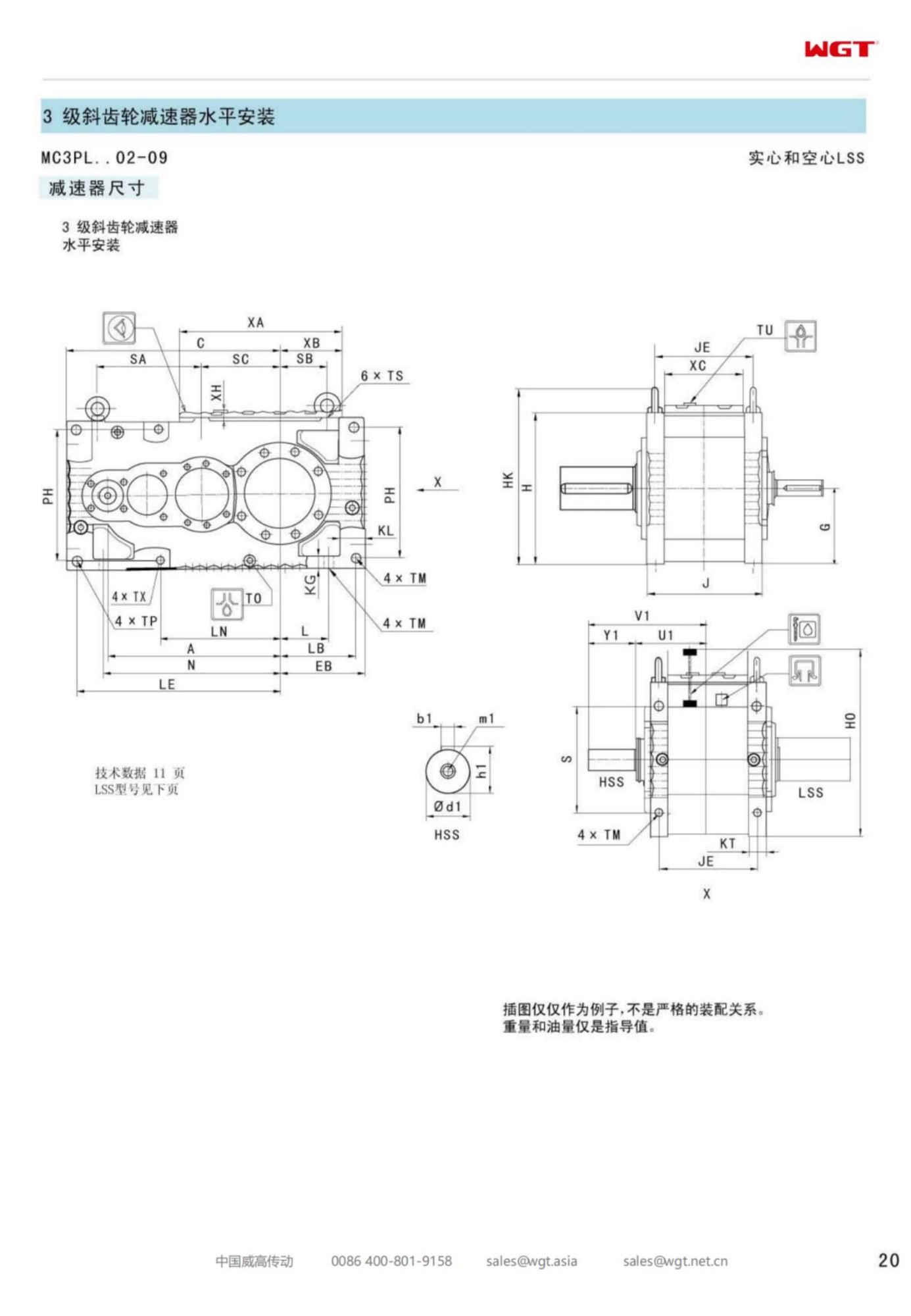
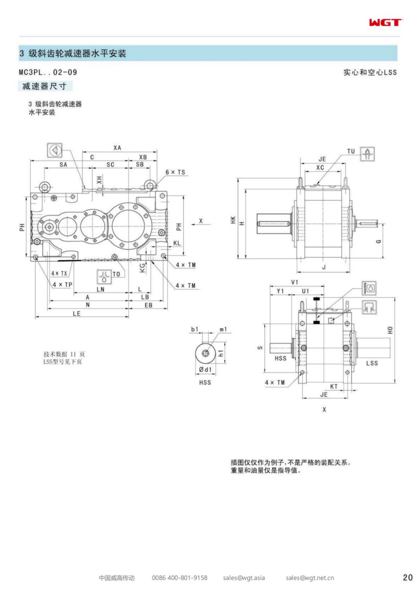
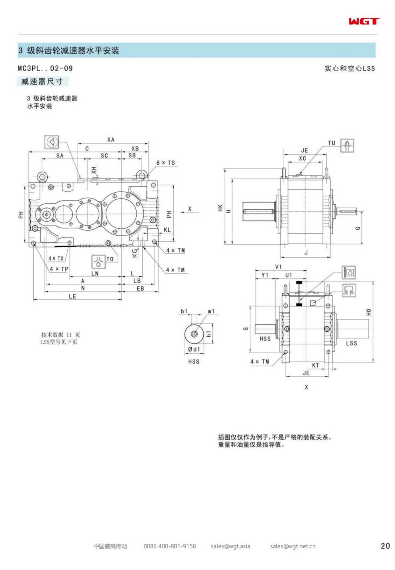
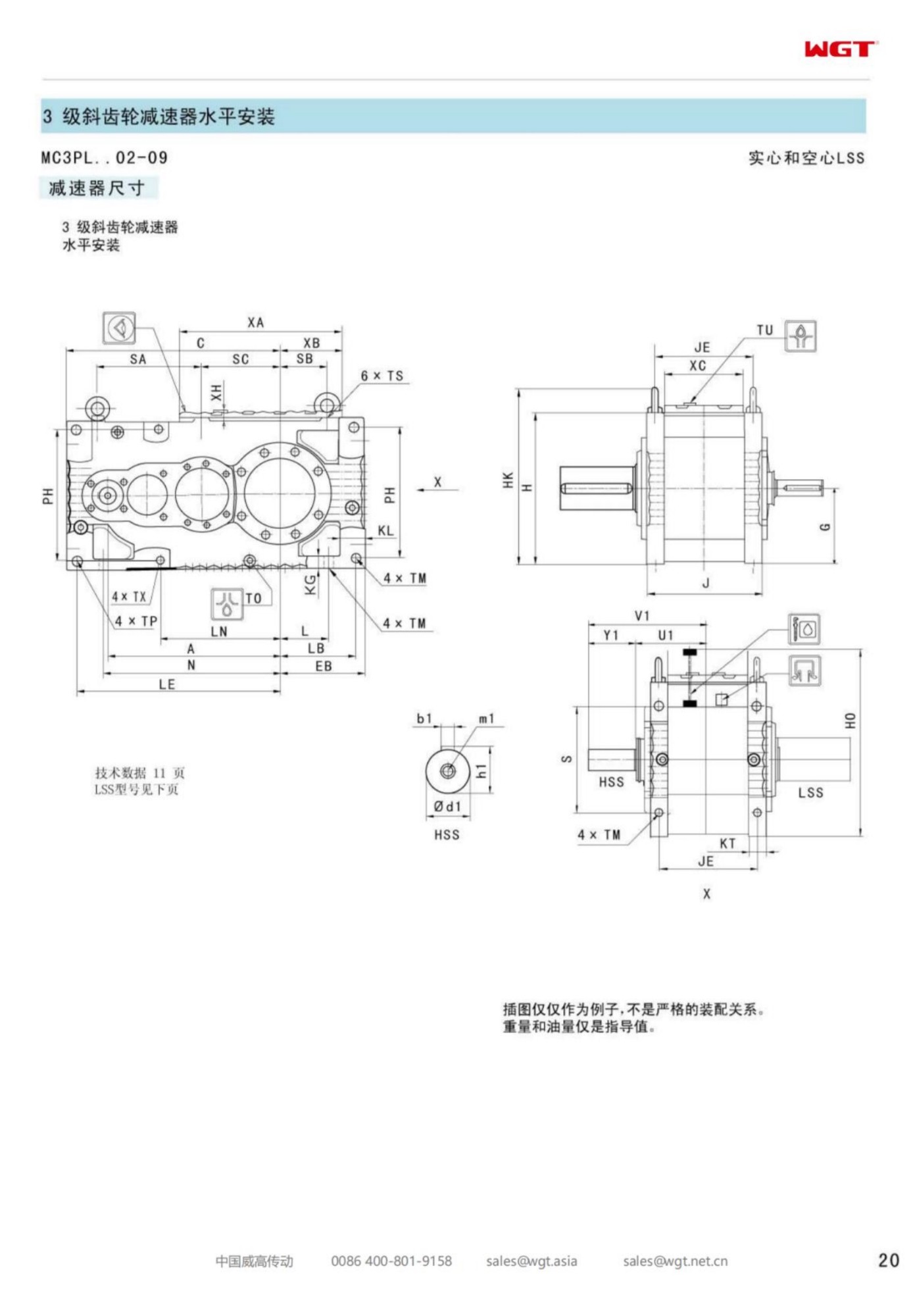
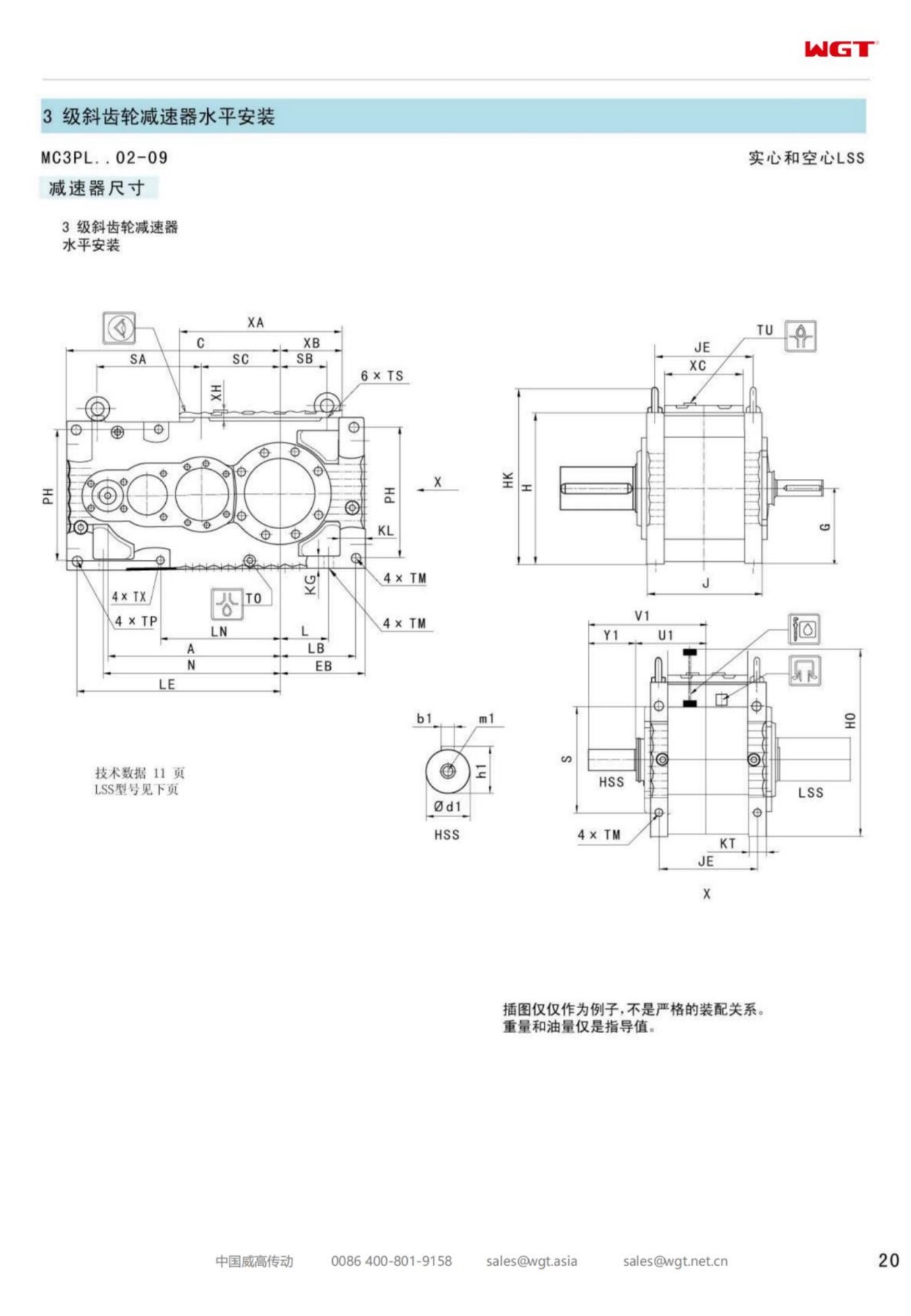
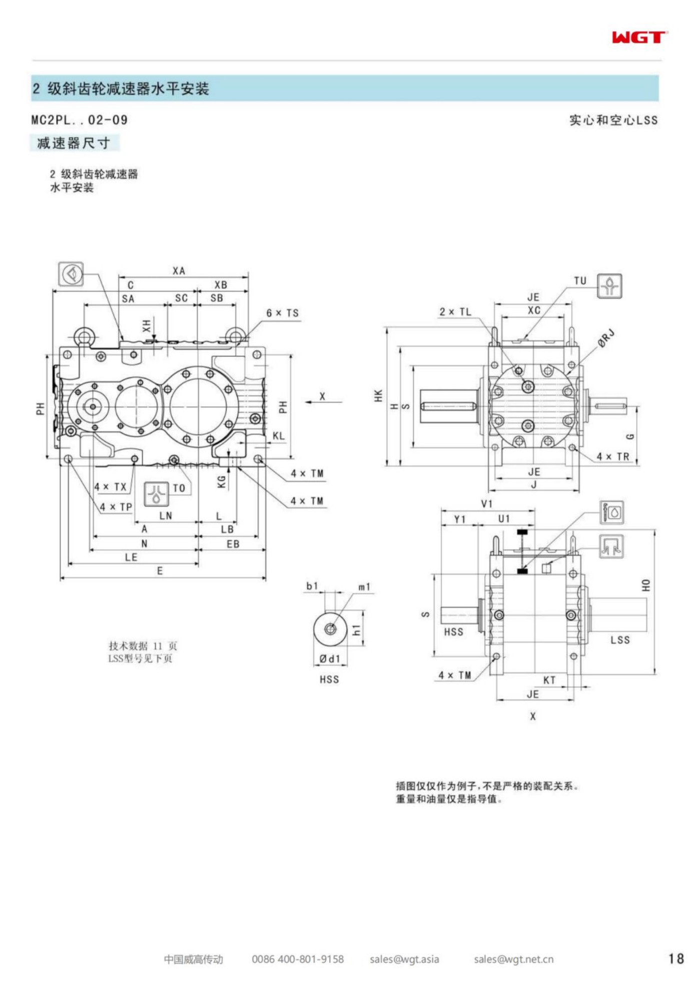
Every band has a frame where duties stop being simple, and in this family that is the third step. Below it, drives are motor, gearbox, machine, in a line, doing one thing at a steady torque. At it and above, the drive line starts collecting passengers: brake discs that ride the coupling, torque limiters guarding fragile processes, flywheels smoothing a crushing stroke, backstops holding an incline. The MC2PLST03 torque arm gearbox is the frame built to carry that traffic - two helical stages and a solid output shaft, with a coupling line long enough to host everything the duty needs.
The construction is the family standard: level case, parallel shafts, an arm taking the reaction so the machine needs no foundation. What frame three adds is margin. Torque capacity with headroom for the peaks that accessory-laden duties produce, thermal capacity for the longer runs those duties usually run, and an output end that treats the coupling as the system's crossroads rather than its afterthought.
Frame Three, Where Duties Stop Being Simple
The pattern repeats across industries. A conveyor that was a straight run acquires a brake after the first unplanned rollback. A feeder that stalled twice gets a torque limiter so the next stall costs a shear element instead of a gearset. A crushing or screening duty adds a flywheel to carry the stroke. None of these is exotic, and all of them arrive after commissioning, which is why the frame at the centre of the band - large enough to be worth upgrading, small enough to be worth upgrading in place - collects more accessory-laden duties than any other step.
The selection consequence is that frame three is rarely chosen on running torque alone. The peaks matter, the accessory losses matter, and the thermal position matters, because a drive carrying brakes and limiters is usually a drive the process depends on hour after hour. A frame specified with a service factor chosen for a simple belt, then handed a duty with starting peaks and accessory drag, is a frame that will run warm and explain itself through its oil.
Decoding MC2PLST03
The string follows the band's grammar; the digit marks the third frame in it.
| MC | Industrial gear unit family for continuous plant service |
| 2 | Two helical reductions in a single gear plane |
| P | Parallel-shaft layout, input and output parallel |
| L | Level build, both shafts horizontal in one case |
| S | Solid output shaft leaving the case through a conventional coupling |
| T | Torque arm reaction, no feet and no foundation |
| 03 | Third frame: the band's mid-light step, where brakes, limiters and accessories ride the coupling |
As an order document the string settles the geometry and leaves the duty's shape to the text: ratio and service factor against the real peaks, the coupling train listed component by component, the brake or limiter's make and calibration if one exists, and the thermal position. Frame three's orders are usually written twice - once for the machine as delivered and once for the machine as it has become - and the second version is the one that runs.
What Rides on the Coupling
Listing the coupling line is the most useful paragraph in an enquiry for this frame, and it is the paragraph most often missing. A brake disc adds rotating mass and a flange joint. A torque limiter adds a mechanism with its own drag and its own maintenance. A flywheel adds inertia that the gearset feels on every start. A spacer coupling adds length that moves the guard and the alignment targets. Each item is ordinary; the sum of them is the difference between a drive line and a drive train, and trains are designed, not assembled.
The practical rule is to draw the line, literally, before the order: shaft to hub, hub to element, element to disc, disc to spacer, spacer to machine. The drawing takes an hour and settles the questions that otherwise surface on site - total length against the real gap, which joint comes apart for service, where the guard splits, which component the crew can reach with a spanner without removing two others. Frame three carries all of it happily; the failure mode is never the frame declining the load, it is the site discovering the train does not fit the space it was sent to.
Brake Discs Between the Machines
A disc on the coupling is the cleanest brake arrangement a plant can own: the disc turns at machine speed, the caliper sits where hands reach it, and holding torque is applied to the slow side where it is worth the most per newton-metre. The gearbox sees the brake as a reaction through the coupling, not as a torque through its gears, provided the brake acts on the output side - which is exactly why discs belong there rather than on the motor alone.
Two details decide whether the arrangement stays clean. The disc's balance and runout, because a slow-speed disc that wobbles announces itself as a once-per-revolution knock the plant will blame on the gearcase. And the caliper's reaction - a caliper bolted to a guard sheet or a bracket that flexes applies the brake to the structure as well as to the disc. Both details are cheap at order time and expensive as diagnosis, and both belong on the commissioning checklist rather than in the memory of whoever fitted them.
Torque Limiters and Machines That Stall
A torque limiter in the line is a promise that the next stall will be a cheap event, and frame three duties are full of machines that stall: feeders meeting tramp material, conveyors choked by a surge upstream, mixers grabbing a stiff batch. The limiter's calibration is a process decision as much as a mechanical one - set it too low and it trips on every heavy start, set it too high and it protects nothing. The gearbox's role is to accept the limiter's world: repeated release events, restart torque against a partially cleared machine, and the occasional operator who holds the machine against the limit to finish a shift.
The selection consequence is a service factor argued from the duty's worst shape rather than its average. A duty with a limiter sees more high-torque events per month than the running current ever suggests, and the gearset that survives such a duty is the one sized for the events. Saying plainly in the enquiry - this machine stalls, here is how often, here is how it restarts - buys more frame life than any margin guessed at afterwards.
Overhung Load Discipline at the Output
A coupled output is kinder to the case's output bearing than a bore lifting the whole case over a shaft, but it is not free of overhung questions. The coupling's weight, any disc or limiter hung beyond it, and the pull of a misaligned machine all land on the output bearing through the shaft end. Frame three carries a generous rating, and the discipline is to keep the heavy passengers close to the case: a limiter mounted outboard of a long spacer converts its own mass into leverage the bearing pays for.
The check is one line in the enquiry - list what hangs on the output end and at what distance - and one habit in service, listening for the bearing tone at the output end during the first months. A passenger added after commissioning, which is how they usually arrive, deserves a second look at the coupling line drawing and a re-check of the alignment, because the train's balance and length changed the day the passenger was fitted.
Balance and Vibration on a Coupled Train
Every flange joint in the train is a chance for a small eccentricity, and every added component is a mass that can sit slightly off centre. Individually these are invisible; together, on a train running thousands of hours, they set the vibration floor the whole drive lives on. The practical response is not laboratory balancing but assembly discipline: follow the maker's clock marks on multi-bolt joints, fit hubs square, and after commissioning take a baseline reading at the case and at the machine so the floor is known.
When the baseline exists, diagnosis is arithmetic. A change in the once-per-revolution component at machine speed points at the coupling train - a worn element, a loose hub, a disc that has picked up mud or product build-up. A change at gear mesh frequency points inside the case. Plants that skip the baseline spend their diagnosis budget arguing about which half of the line is speaking, and frame three's train has more halves than most.
Duty Profiles That Belong on Frame Three
Positions that hang brakes, limiters and flywheels on the drive line:
- Apron feeder drive under a primary crusher at a cement plant
- Conveyor head drive at a phosphate washing plant with a brake disc on the coupling
- Inclined shuttle conveyor drive at a sinter handling bay in a steel works
- Sludge cake conveyor drive at a municipal dewatering building
- Reclaim feeder drive under a long-term stockpile at a potash mine
- Gantry transfer conveyor drive at a malting plant
What these positions share is a duty that grew: a machine that acquired a brake, a limiter or a heavier feed after the original drive was chosen. Frame three is where the band absorbs that growth without the plant re-engineering the mounting.
The Torque Arm at Mid-Band
The arm's job grows with the frame. Reaction torque rises step by step through the band, and at frame three the arm and its bracket are carrying enough load that their condition is part of the drive's health, not just its mounting. The bushings and pins go on the stop-by-stop inspection list; the bracket gets checked for flex and fretting at the weld line; the fasteners get a torque wrench rather than a workshop habit.
The arm also remains the frame's best argument. An accessory-laden drive train is exactly the installation that dreads a re-alignment project, and the arm holds the case steady without any foundation work at all. Shims stay labelled, alignment numbers stay on record, and the frame keeps its geometry for years of stop-and-go duty that would walk a lesser mounting out of tolerance.
Thermal Position at Frame Three
Frame three sits where thermal rating starts to shape selections. Duties at this step run long hours - the conveyors, feeders and elevators that grew their accessories grew them because the process leans on them - and the heat a drive soaks has to leave through the case. The ordinary ladder applies: clean case and free air first, a shaft fan where the ambient allows, a larger sump where dwell time helps, and forced cooling above that. The mistake is selecting the thermal position for the design month and meeting the worst month with a drive that has no margin left.
One line of the enquiry settles most of it: the highest ambient the drive actually sees, under cladding, in summer, with the machine running flat out. Select against that number and the frame's oil temperature will sit in a band the plant can monitor; select against the average and the drive becomes a seasonal argument that the oil samples will eventually win.
Spares That Actually Get Used
Frame three's spare-shelf logic is easy to get wrong in both directions. The parts that genuinely earn their shelf space are the coupling element, the arm's bushings and pins, the seal set and the breather - consumables in the true sense, cheap enough to stock and certain to be needed. A complete spare gearcase for a frame this size is rarely the right answer; the lead time on an exchange unit is usually shorter than the decades a well-run frame lasts between overhauls.
What the plant does need is the documentation that makes the waiting time short: coupling drawings with the element part number, seal and bearing references, and the tightening figures for the arm and bracket hardware. A drive that goes down with a failed element and returns in four hours was prepared by paperwork, not by a shelf. Frame three rewards that preparation more than the smaller frames, because its duties are the ones the plant notices stopping.
The Enquiry for a Coupled Drive
The enquiry that gets this order right is a drawing and a story. The drawing is the coupling line, component by component, with distances. The story is the duty: the machine, its material, the motor and speeds, the ratio target, the stalling history, the brake and limiter if they exist, the ambient and hours, the shaft measured honestly and the gap measured exactly. Neither half is optional - the drawing without the story produces a frame with no margin for the peaks, and the story without the drawing produces a frame that does not fit the space.
Sent complete, it returns a selection with the service factor argued from the duty's worst day, a thermal position that holds in summer, and a coupling train specified rather than improvised. Frame three has carried accessory-laden duties for decades with exactly that enquiry behind it, and the plants that write it once keep it updated - because on this frame, the line between the case and the machine is where the engineering lives.
The M3 Series at a Glance
| Model | Centre distance | Output | Typical duty |
|---|
| M3PSF50 | size 50 | solid shaft, foot | conveyors, feeders |
| M3PSF60 | size 60 | solid shaft, foot | crushers, mixers |
| M3PSF70 | size 70 | solid shaft, foot | ball mills, shredders |
| M3PSF80 | size 80 | solid shaft, foot | kilns, heavy conveyors |
| M3PSF90 | size 90 | solid shaft, foot | mill and kiln drives |
| M3RSF50 | size 50 | solid shaft, foot, right-angle | inclined conveyors, elevators |
| M3RSF60 | size 60 | solid shaft, foot, right-angle | screw classifiers, feeders |
| M3RHF70 | size 70 | hollow shaft, foot, right-angle | agitators, drum drives |
| M3PHT80 | size 80 | hollow shaft, torque arm, parallel | shaft-mounted conveyors |
| M3RHT90 | size 90 | hollow shaft, torque arm, right-angle | heavy shaft-mounted drives |
All frames in the table belong to one industrial family. P = helical parallel-shaft, R = bevel-helical right-angle; the low-speed shaft is solid (S) or hollow (H), mounted on feet (F) or a torque arm (T).
Selection Example: Apron feeder drive under a primary crusher at a cement plant
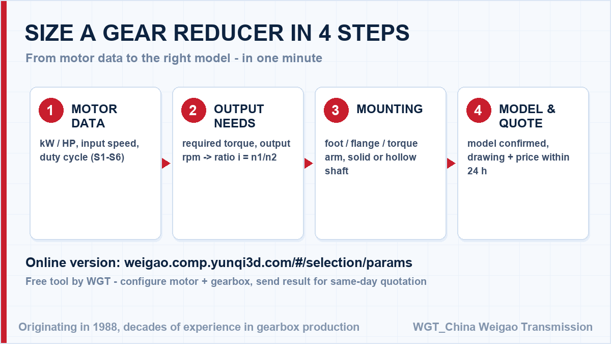
Take a 45 kW motor at 1480 rpm turning the feeder at 24 rpm. The ratio follows directly: 1480 / 24 = 61.7, so a ratio near i=62 sits in the upper part of the two-stage band, and the frame is sized against the shock peaks a jammed apron feeder delivers rather than running torque alone. In this case frame three takes the peaks with margin, and the solid output shaft accepts the limiter and the flywheel the duty has grown over the years. That single division gives the catalogue ratio; the service factor for your duty class is then applied to the torque, and the frame size follows.
![how to size a industrial helical gearbox in four steps]()
Sizing flow: motor speed, target output speed, torque, service factor.
Where This Series Works in Practice
Wood chipper line
A board mill drives its drum chipper with a heavy-duty gear unit. Knife engagement shocks arrive several times a second, and the case-hardened gearing with generous bearing spans has shown no measurable wear.
Fertiliser plant drag chain
A fertiliser complex runs drag-chain conveyors on industrial gear units in a corrosive atmosphere. The heavy-duty epoxy coating and FKM seals have kept the units presentable and leak-free through several campaign cycles.
Technical Questions, Answered
What ambient and altitude limits apply?
The standard build suits -10 to +40 degrees C at altitudes below 1,000 m with the supplied oil grade. Colder sites get synthetic oil and heaters; high altitudes or hot climates may call for the next frame size or forced cooling.
Do you supply the unit with an electric motor fitted?
We deliver the bare gear unit with an input suitable for your motor, or as a complete motor-gearbox assembly aligned and tested at the works. For upgrade projects many customers keep the existing motor and order the unit alone.
![industrial helical gear reducer application fields]()
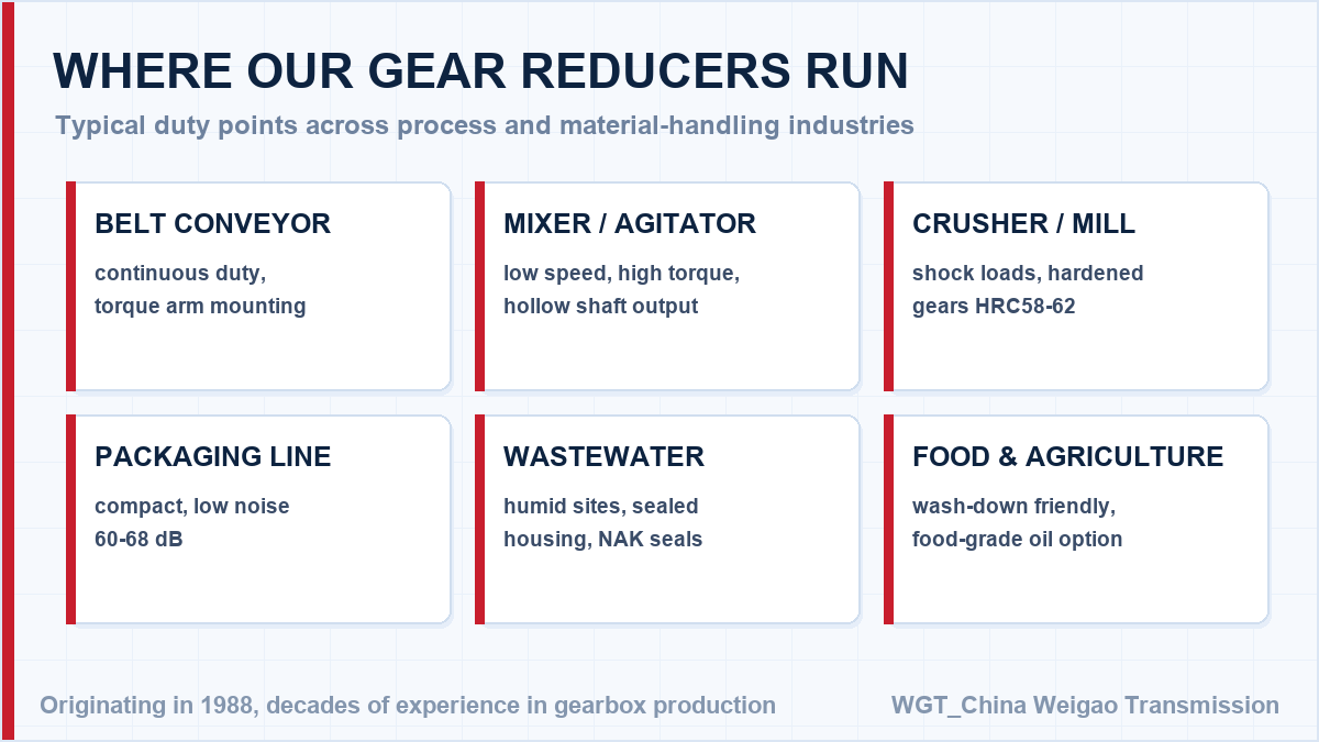
Common application areas for right-angle industrial helical drives.
Duty Data In, Firm Model Out
Three numbers decide it. Skip the back-and-forth: configure your drive in the WGT Motor & Gearbox Online Selection System and send us the result for a same-day quotation.
Motor power and speed, required output speed and the driven-machine description fix the selection. Send them and the confirmed model, service factor and price come back in writing the same day. Looking for a speed reducer for cement plant? Tell us the duty point and we will confirm the model in writing.