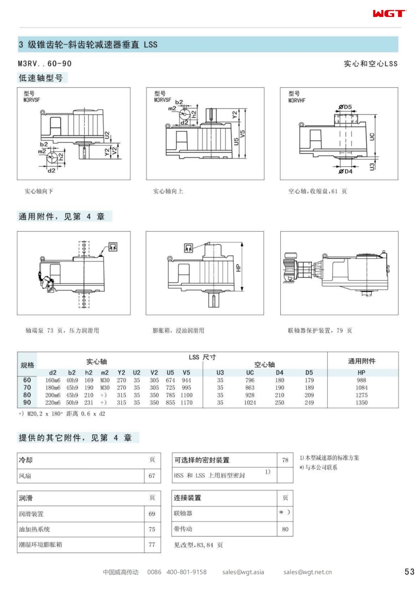
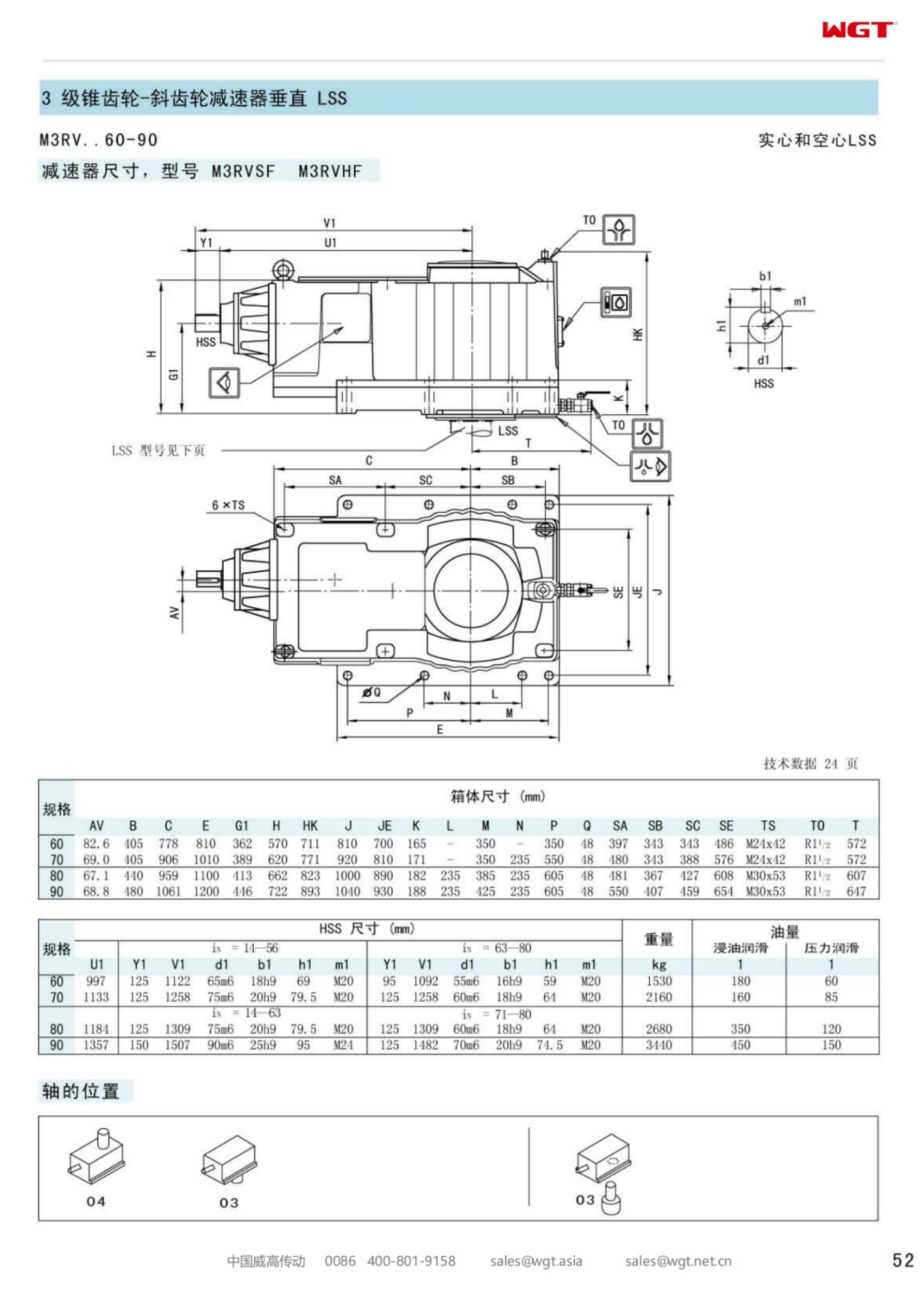
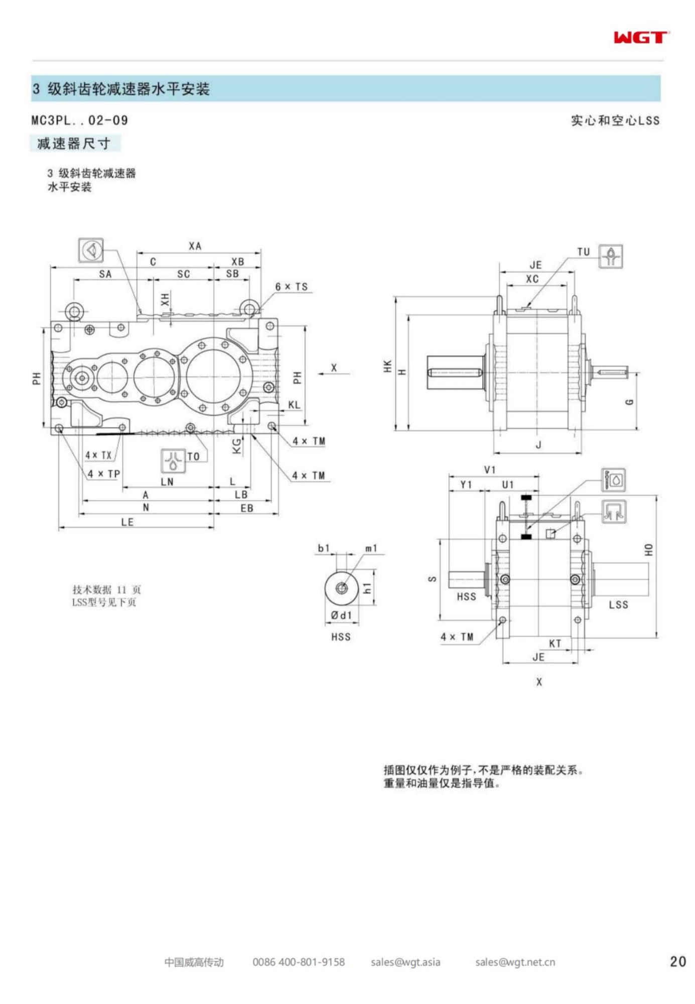
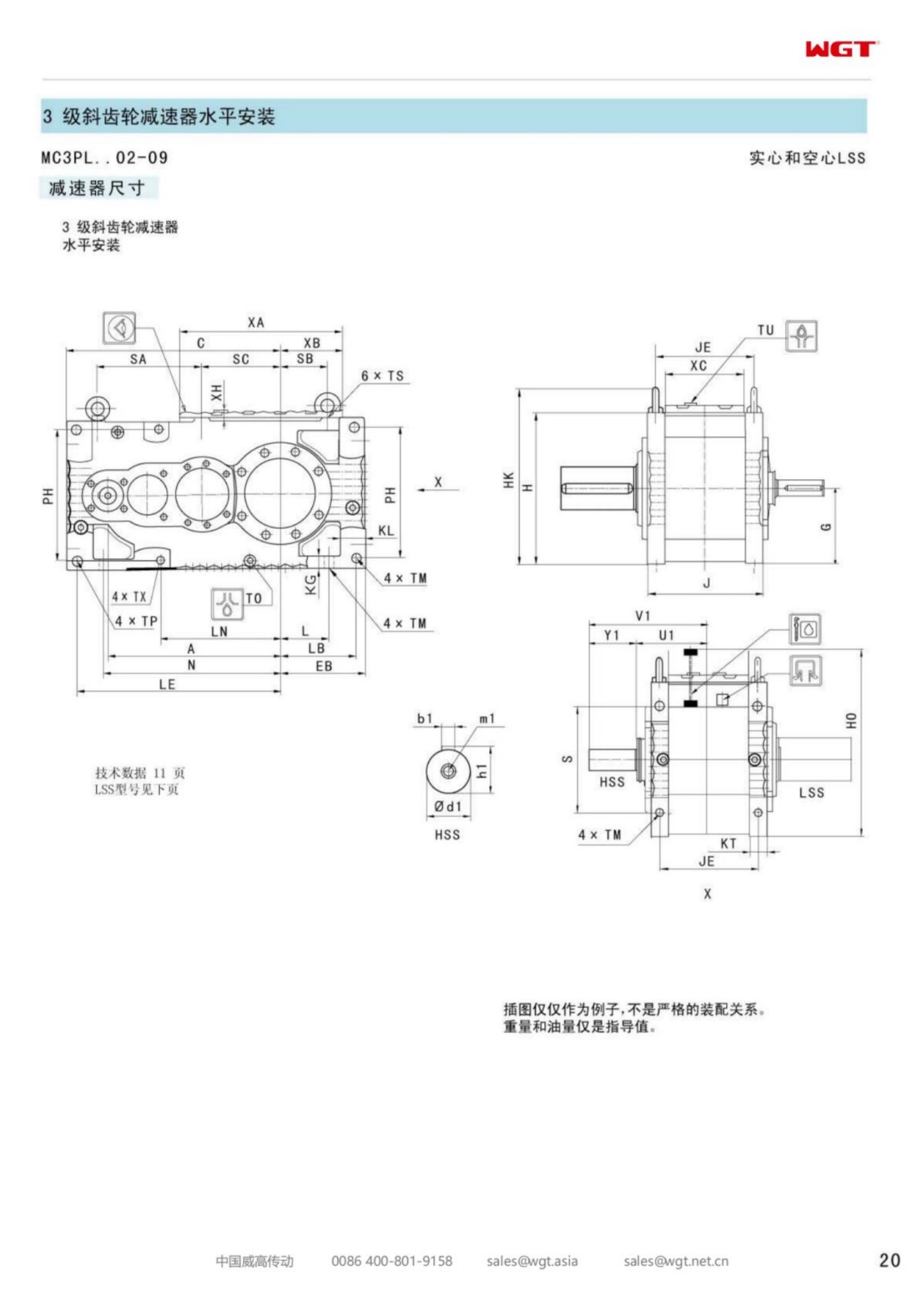
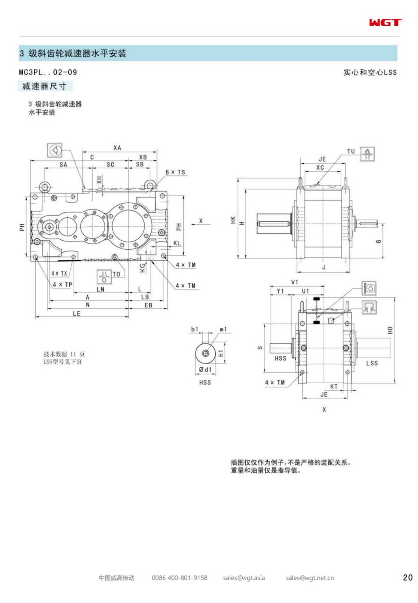
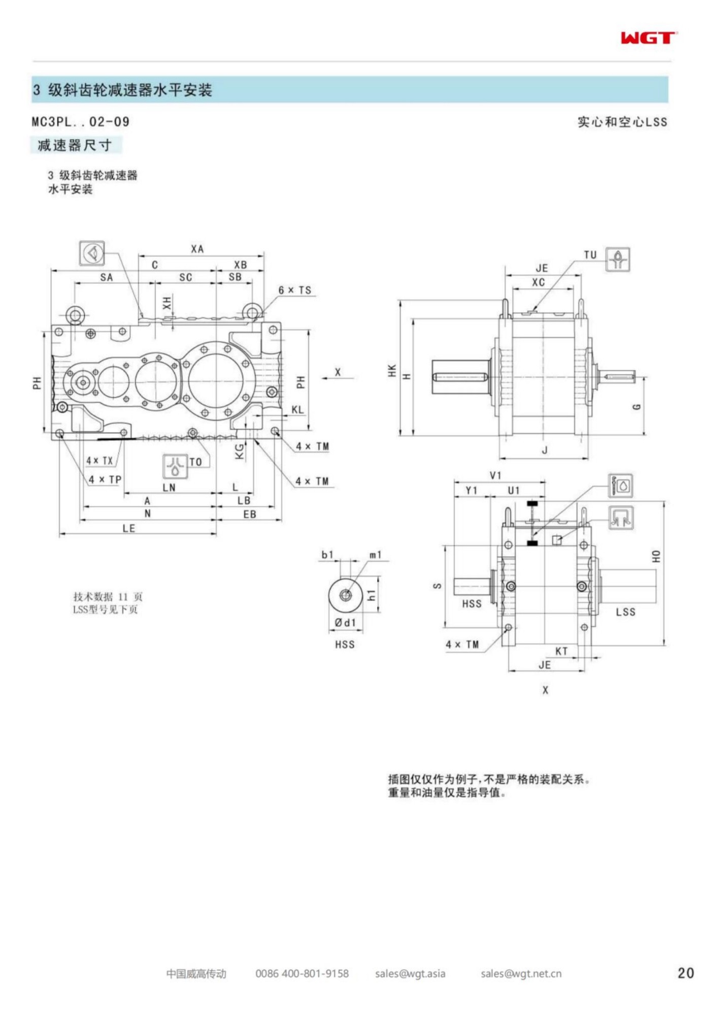
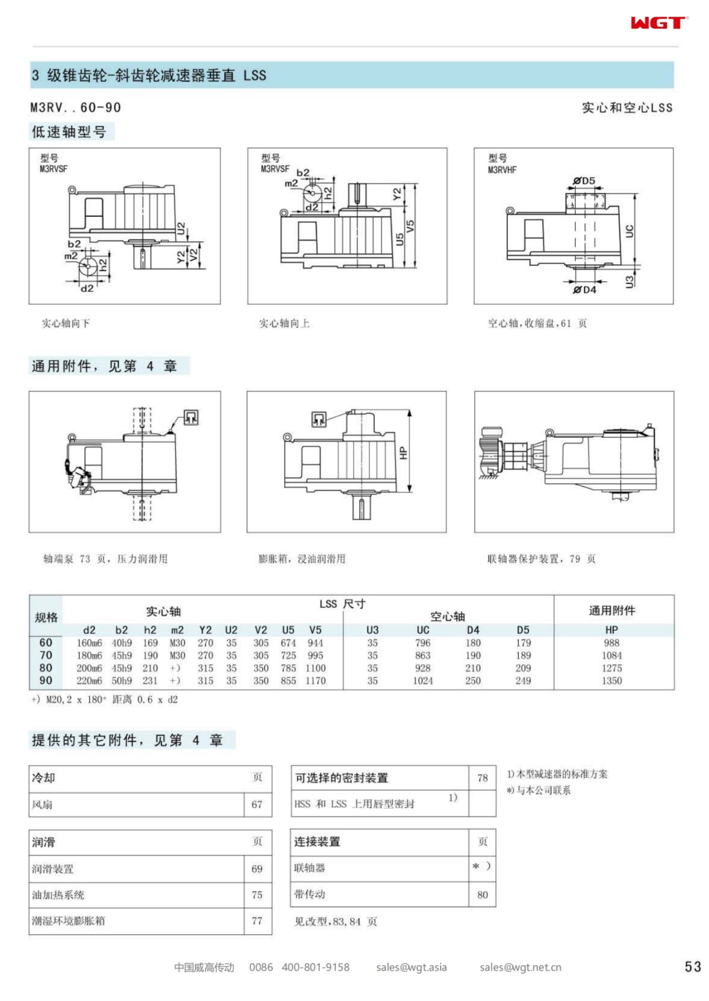
The M3RVSF80 vertical bevel helical gear unit is the point in the upright range where the housing stops being a small casting and becomes a load-bearing structure. A lapped spiral bevel stage takes the input from the side, two ground helical stages bring the speed down, and the solid output shaft leaves the bottom face pointing straight at the process. Everything the drive needs to stay aligned - bearing seats, flange face, seal bore - is machined in one piece, so a rotating column of several metres hangs from a reference that cannot move relative to itself.
What the 80 Frame Is Actually For
Enquiries that land on the 80 build usually share one feature: the process shaft has become long. Long columns generate bending moments that scale roughly with the square of the overhang, and those moments arrive at the gearbox as a tilting load on the lower bearing rather than as clean torque. A frame below this one can be geared for the torque and still be wrong for the duty, because the bearing seats are sized for a shorter insertion depth. Checking the overhung load against the catalogue curve before fixing the frame is the step that keeps a perfectly adequate ratio from failing at the seal.
There is a second, quieter argument for the 80: service access. On a large headplate, the distance between bolt centres and the clearance around the output flange decide whether a seal can be changed from a platform or from a rope. Larger frames buy working room with the same flange pattern language, which is why plants standardise on one frame after the first is installed.
Reading the Code as a Machining Instruction
| M | Industrial multi-stage gear unit range |
| R | Right-angle entry through a spiral bevel pair |
| V | Upright housing, output face downwards |
| S | Solid ground shaft with key, no bore |
| F | Foot pads plus flange face for headplate fixing |
| 80 | Frame size, third step in the upright family |
The digits after the letters are not a ratio and must not be read as one. They set the casting, the bearing set and the shaft diameter; the ratio is a separate figure on the nameplate, and two 80 units with quite different ratios share the same foot pattern. Ordering by frame plus ratio plus arrangement is the only combination that produces a repeatable article.
Oil Management on a Tall Housing
A tall upright housing separates into two oil regions: a sump at the bottom that the lowest bearing sits in, and upper gears that are oiled by what the rotating parts throw upward. On an 80 frame the vertical distance between those regions is large enough that a short fill leaves the top stage running dry while the sump still reads acceptable. The only reliable check is the sight glass or dipstick read with the unit stopped and level, then compared with the quantity printed on the plate.
Breather placement matters for a different reason. In a housing that cycles between warm running and cold idling, the air space breathes in and out several times a day; a breather mounted where condensate gathers pulls water in with that breathing. Fitting it at the highest practical point, and checking it during the first month rather than the first year, prevents the milky oil that gets blamed on the supplier.
Service profiles this build is regularly chosen for: Vertical turbine pumps at river intake stations Agitators on anaerobic digester roofs Screw conveyors lifting screenings out of wet wells Crystalliser stirrers in soda ash plants Sludge thickener drives at mine water treatment Mixing units on de-icing salt brine tanks Vertical roller mill separators in lime grinding Froth column stirrers in mineral flotation circuits
Setting the Unit Down for the First Time
Test stand running happens at the factory, in the posture the unit will work in, and the crate leaves oil filled. The site job is therefore an alignment job rather than an assembly job. Check headplate flatness across the bolt circle, not just at one edge; a plate that is flat in the middle and dished at the rim tilts the housing and puts a permanent side load on the output seal. Lower the unit, snug the flange bolts in a crosswise pattern, then torque in the sequence marked on the flange. Connect the process shaft last so that any residual misalignment shows up as a shaft run-out rather than as a housing distortion.
Rotate by hand before energising. A hand turn that is smooth but stiff usually means a coupling misalignment; one that binds at a single point in the revolution means something in the column is out of true. Run unloaded for several minutes, watch the seal for weeping and listen at the inspection cover for a dry upper stage, then load up gradually and record oil temperature at steady state.
Specification Data the Factory Needs
Send output torque or motor rating, output speed, overhung load and its point of application, shaft direction, mounting posture, medium and ambient temperature, and the daily running hours. Add the shaft diameter and fit at the process coupling, because the gearbox bore or key must be machined to suit the part already on site. A photograph of the old nameplate shortens the exchange more than any form, and a sketch of the headplate removes the last guesswork about flange drilling.
Spares Philosophy for a Standardised Line
Where a plant runs several vessels at similar duty, the cheapest long-term decision is often to hold one seal kit and one oil grade across the whole line. That only works if the frames are the same, so it is worth deciding at specification stage whether the largest duty on the line should set the frame for all of them. The first cost rises; the number of part numbers in the stores falls; and a night-shift repair stops depending on which crate happens to be on the shelf.
Available Frames and Their Typical Duty
| Model | Centre distance | Output | Typical duty |
|---|
| M3PSF50 | size 50 | solid shaft, foot | conveyors, feeders |
| M3PSF60 | size 60 | solid shaft, foot | crushers, mixers |
| M3PSF70 | size 70 | solid shaft, foot | ball mills, shredders |
| M3PSF80 | size 80 | solid shaft, foot | kilns, heavy conveyors |
| M3PSF90 | size 90 | solid shaft, foot | mill and kiln drives |
| M3RSF50 | size 50 | solid shaft, foot, right-angle | inclined conveyors, elevators |
| M3RSF60 | size 60 | solid shaft, foot, right-angle | screw classifiers, feeders |
| M3RHF70 | size 70 | hollow shaft, foot, right-angle | agitators, drum drives |
| M3PHT80 | size 80 | hollow shaft, torque arm, parallel | shaft-mounted conveyors |
| M3RHT90 | size 90 | hollow shaft, torque arm, right-angle | heavy shaft-mounted drives |
Note that PSF and RSF frames of the same size share the mounting footprint; the R build simply inserts a bevel stage, so switching layout rarely forces a foundation change.
Questions and Answers
Do you supply the unit with an electric motor fitted?
We deliver the bare gear unit with an input suitable for your motor, or as a complete motor-gearbox assembly aligned and tested at the works. For upgrade projects many customers keep the existing motor and order the unit alone.
How is the gear unit protected against dust and moisture?
Housings are gasket-sealed with labyrinth or lip seals at both shafts as standard. Dusty plants, washdown areas and outdoor installations are covered by coating and sealing options specified together with the order.
What inspection access does the housing provide?
The horizontally split housing opens along the shaft centreline, so gearing and bearings can be examined without removing the unit from its foundation. Covers give access to the oil galleries and bearing seats during service.
Installation Examples
Glass batch charger
A float-glass line drives its batch charger with units. Abrasive raw material demands a robust drive, and the case-hardened gears show minimal wear after years of continuous operation.
Battery slurry mixer
A battery materials plant uses reducers on slurry mixers. High shear loads are absorbed by the 42CrMo shafts, and the 94-96% efficiency keeps motor sizing and running cost down.
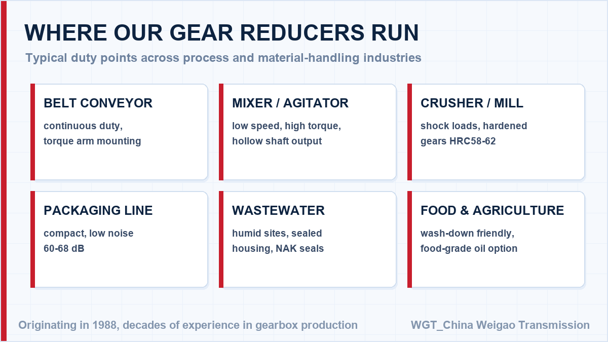
![gear box application map for industry]()
From quarries to food plants - one right-angle drive concept.
Selection Example: Typical duty point
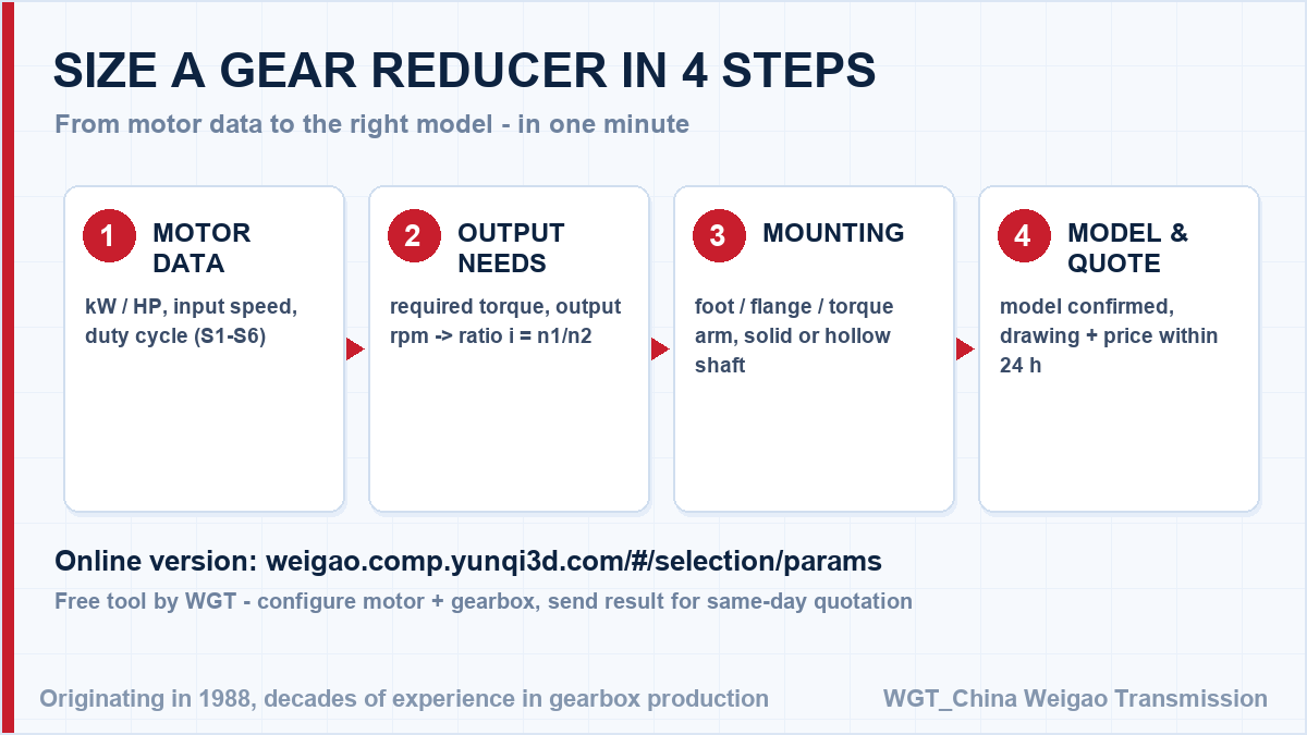
Take the common case - a machine that must be driven well below motor speed. Motor speed divided by the target output speed gives the ratio, rounded to the nearest available step, and the required torque with the service factor then fixes the frame size. The ratio is the easy part. The service factor for the shock level is what makes the selection safe, and we check that for you at no charge.
![how to choose a speed reducer model]()
Ratio first, then torque, then frame size: the standard selection route.
Full Documentation for Project Tenders
Bidding a project? The WGT Motor & Gearbox Online Selection System covers motor power, ratio and mounting on one screen - enter your numbers and see the model immediately.
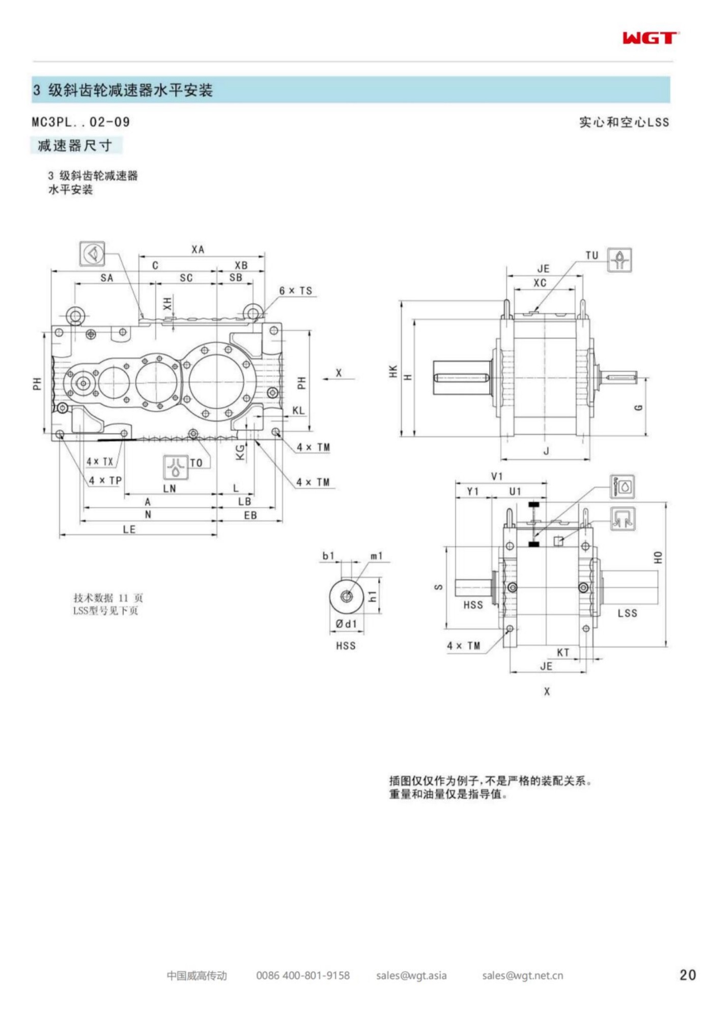
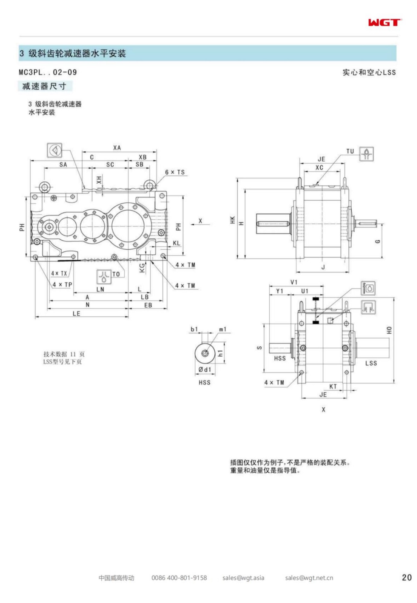
We support tenders with complete technical files: dimension drawings, rating tables, material certificates and test record formats, in the format your client specifies. Looking for a gearbox for wastewater treatment? Tell us the duty point and we will confirm the model in writing.