


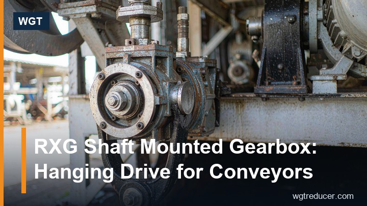
RXG Shaft Mounted Gearbox: Hanging Drive for Conveyors
A shaft mounted reducer solves one specific problem: a conveyor or elevator has a head shaft strong enough to carry the drive, and no floor, plinth or coupling space to spare beside it. The RXG series is built for exactly that position - it hangs on the machine's own shaft, reacts its torque through an arm bolted to the frame, and needs neither a foundation nor an alignment session.
This guide covers what the RXG family is, how to read its sizes, when it beats a foot mounted unit, and the three numbers that actually decide the selection. It is written for the buyer who has to specify one, and for the fitter who has to make it run quietly.
What an RXG Shaft Mounted Gearbox Is
The RXG is a helical shaft mounted gearbox: a hollow output bore that slides over the driven shaft, a helical gear train that reduces motor speed to a low output speed, and a torque arm that absorbs the reaction. There is no output coupling, because the machine's shaft is the output. The motor mounts on the input side through a flange or a motor bracket, so the complete drive is a single assembly hanging on the equipment.
The lineage matters here. The series was developed for quarry and mine duty, where conveyors run in dust, start loaded, and are expected to keep running without a maintenance team standing over them. That origin explains the design priorities: a stiff case, generous bearings, an oil bath that tolerates a range of mounting angles, and - on inclined installations - the backstop option that stops a loaded belt from running backwards when the drive is switched off.
Published limits for the family give the shape of the range: input speeds up to about 2000 rpm and output speeds up to roughly 400 rpm, with the largest frames rated in the tens of thousands of newton-metres of output torque. Those are envelope figures, not a selection - the duty, not the catalogue, decides the frame.
Sizes, Ratios and What the Nameplate Tells You
The RXG range runs from small frames in the thirties to the largest at 100, plus geared variants such as RXG35-125 where the trailing number carries the nominal ratio. The size digit is not a power rating; it is a frame designation that sets bore diameter, centre distance, bearing capacity and case mass together. Two units of the same size can be built for very different torques and speeds depending on the internal ratio.
| Field on the nameplate | What it fixes | Why a buyer should read it |
|---|---|---|
| Series and size (RXG50, RXG80) | Bore diameter, centre distance, bearing size, case mass | Decides whether the unit fits the shaft and the space |
| Nominal ratio (e.g. 125 in RXG35-125) | Output speed at a given motor speed | Sets belt or chain speed; the ratio must match the process, not the motor |
| Motor power and speed | Input side of the torque calculation | The same frame can carry different powers at different speeds |
| Mounting position | Oil level plug, breather location | A unit filled for the wrong attitude runs hot or starves |
| Backstop fitted or not | Whether reverse rotation is blocked | Mandatory reading on any inclined conveyor |
The practical rule: quote the size and the ratio whenever you order a spare or compare quotations. A price for "an RXG60" without a ratio is not comparable with anything, and a spare that arrives at the wrong ratio will fit perfectly and run the belt at the wrong speed.
Shaft Mounted or Foot Mounted: the Real Trade
Both arrangements do the same job. The difference shows up in civil works, access and the maintenance plan.
| Consideration | Shaft mounted (RXG type) | Foot mounted with coupling |
|---|---|---|
| Foundation | None - hangs on the driven shaft | Plinth or fabricated base, grouted and levelled |
| Coupling | None to buy, guard, align or inspect | Coupling, guard, alignment record |
| Floor space | Effectively zero at the drive point | Reserved area beside the machine |
| Installation time | Hours, with a chain block | Days, with concrete cure time |
| Load path | Drive shares the driven shaft and its bearings | Drive carries its own loads on its own base |
| Reaction handling | Torque arm into the machine frame | Feet into the foundation |
| Best fit | Conveyor head shafts, elevator head shafts, screw conveyor tails | Large drives, high overhung loads, drives needing a solid base reference |
| Servicing | Unit slides off the shaft; shaft must have plain length to spare | Unit lifts off its base; coupling must be broken first |
Two honest limitations. First, a shaft mounted unit inherits the driven shaft's deflection - if the shaft is marginal, the gearbox bearings see it. Second, the reaction has to land on structure that can take it, and the bracket is usually designed by whoever is holding the machine drawing, not by the gearbox supplier. Get those two right and the arrangement is the tidiest drive on the site. Ignore them and the vibration report will blame the gearbox for a year.
Sizing a Conveyor Drive With Three Numbers
Selection comes down to output speed, output torque and service factor. The arithmetic is simple enough to do on the back of a drawing.
Output speed follows from the process: belt speed divided by pulley circumference, or chain speed divided by sprocket pitch diameter. Torque at the head shaft comes from the pull the belt needs: torque (N·m) equals belt pull (N) multiplied by pulley diameter (m), divided by two. Motor speed divided by required output speed gives the ratio, and ratio plus torque plus service factor gives the frame.
The service factor is where quotations diverge. A uniformly loaded conveyor might sit near 1.0-1.25; a belt that starts full, a screw that empties a silo, or a chain that jams will ask for 1.5 or more. Multiply the running torque by that factor before comparing frames, and state the start condition in words - "started loaded after a weekend stop" tells the selection engineer more than any single figure.
Three inputs that buyers most often leave out: starts per hour, the worst material condition (wet, frozen, bridged), and the true overhang beyond the bore - any sprocket or sheave hanging past the output adds a bending load the rating never assumed.
The Torque Arm, the Backstop and the Options Worth Ordering
The torque arm is the component that decides whether the installation stays quiet. It must be stiff in the direction of the reaction and free in the others, which is why the connection uses a bushing or a resilient element rather than a rigid welded bracket. Anchor it to structure designed to take a torque - not to guarding, not to a handrail post.
On any inclined conveyor, the backstop is not an option but a requirement. It prevents the loaded belt from running backwards through the gear train when the motor stops, which protects both the drive and anyone standing below the incline. Specify the rotation direction at order time, because a backstop is built for one direction only, and confirming it after delivery means a rebuild.
Other choices worth settling before the case is cast: the motor mounting arrangement (flange, bracket, or a matched gearmotor), the oil level and breather position for the installed attitude, the paint system for wet or coastal air, and whether a shrink disc or a keyed bore suits the shaft. Each is a line on the order confirmation and a week of delay if it is decided afterwards.
If the duty is a large one, the same mounting logic is available in heavier industrial frames - see the MC2PLHT03 torque arm gearbox for a two-stage parallel-shaft build with a hollow bore and foot-free mounting.
Installing One Properly: the Sequence That Matters
Installation is short, and the order of the steps is what makes it short.
First, measure. Shaft diameter in two planes at three positions along the engagement length, keyway condition, and the plain length available beyond the bore so the unit does not bottom out. Second, clean and prepare both surfaces - a dry bore and a dry shaft will fret, and fretting is the failure that looks like a manufacturing fault and never is. Third, slide the unit on with its weight supported, never hanging on the bore edges.
Then fit the key or clamp the shrink disc to the specified torque, set the torque arm at mid-travel with the machine at rest, and confirm the oil level at the plug for the attitude actually installed, with the breather at the high point. Finally, check rotation direction before coupling the process, and guard the rotating parts so that the level plug, breather and arm bushings stay reachable without tools. A guard that must be unbolted for an oil check becomes a guard that is left off.
Maintenance for a Drive Nobody Watches
These drives sit on gantries and head frames, visited when something is wrong rather than on a schedule. That is precisely why the routine has to be short enough to survive contact with a busy shift.
| Interval | Check | What it catches |
|---|---|---|
| Weekly | Oil level, breather clear, seal area dry, arm bushings intact | Leaks, condensation, a loose reaction arm |
| Monthly | Case temperature at the marked patch, noise at usual load, guard secure | Thermal drift, mesh or bearing distress, guard damage |
| First oil change (a few hundred hours) | Drain, inspect the plug magnet, refill to the correct grade | Running-in wear particles before they circulate |
| Annually | Oil sample, bore and key inspection, backstop function test | Wear trend, fretting at the bore, backstop sprag condition |
Records matter more than the checks. A temperature written down at commissioning turns every later reading into a trend, and a trend lets a bearing be changed on a planned weekend instead of an unplanned night. One page per drive is enough; the plants that keep it diagnose over the phone, and the plants that do not re-learn every machine from scratch.
Common Questions
What is the difference between an RXG shaft mounted gearbox and a foot mounted reducer?
The RXG hangs on the driven shaft and reacts torque through an arm, so it needs no foundation, no coupling and no alignment. A foot mounted reducer sits on a base and drives through a coupling. The shaft mounted arrangement saves civil work and floor space; the foot mounted arrangement isolates the gearbox from the driven shaft's deflection.
Can an RXG unit be mounted at an angle?
Yes, within the range the supplier confirms for the specific frame, but the oil level plug and breather position must match the installed attitude. Always state the mounting angle on the enquiry - a unit filled to the wrong plug runs either starved or over-full.
Do I need a backstop on a horizontal conveyor?
Usually not. On any incline, or where a loaded belt could run backwards when power is removed, a backstop is required, and it must be specified for the direction of rotation the duty uses.
How do I know which size to order?
From output speed, output torque multiplied by the duty's service factor, and the shaft diameter the bore has to accept. Send those three plus the start condition, and the frame follows; ordering by motor power alone is how units end up one size too small.
Can the unit be swapped without moving the conveyor?
Only if the layout allows it. The driven shaft needs plain length beyond the bore for the unit to be drawn back, and the torque arm needs to be releasable without dismantling guarding. Both are decided at the drawing stage and cost nothing then.
The Bottom Line
The RXG series earns its place wherever a conveyor head shaft is already the strongest element in the drive line. It removes a foundation, a coupling and an alignment job from the project, and in exchange it asks for two things: an honest service factor and a reaction bracket that can take a torque.
Get the sizing right and the installation is an afternoon's work followed by years of quiet running. Work through the numbers with our online selection tool - output speed, torque and duty - or send the conveyor details and we will confirm the frame, ratio and service factor in writing before you commit to a purchase order.
