


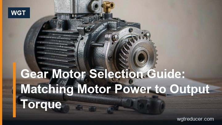
Gear Motor Selection Guide: Matching Motor Power to Output Torque
A gear motor - motor and gearbox delivered as one matched unit - is chosen correctly when three numbers agree: the power the driven machine absorbs, the speed it needs, and the torque the gearbox must carry once the service factor has been applied. Get those three into one calculation and the gearmotor selection stops being a guess; skip any of them and the mistake usually appears as an overheating motor, a stripped keyway or a gearbox that hums its way to an early overhaul.
This gear motor selection guide walks through the sequence in the order a real enquiry arrives: define what the machine demands, run the motor power calculation, fix the ratio, apply the service factor, then match the motor and gearbox interfaces. It closes with the questions buyers ask most often.
What a Gear Motor Actually Packages
A gear motor bolts a standard electric motor onto a speed reducer - helical, worm, bevel-helical or planetary depending on the duty - so the drive arrives aligned, coupled and filled with oil, with no baseplate design, no coupling selection and no on-site alignment session. The gearbox accepts the motor either through a machined IEC or NEMA input flange or through a foot-mounted arrangement with an external coupling.
The appeal is practical rather than cosmetic. Machine builders save envelope space because the motor slides into the gearbox instead of sitting beside it. Purchasing teams order one part number instead of three. And maintenance crews inherit a drive whose motor and gear ratings were checked against each other at the factory - the most common sizing mistake, pairing an undersized gearbox with a generously sized motor, is largely designed out.
The trade-off is flexibility. A separate motor and reducer can be mixed and matched, repaired independently and re-used across projects. A gear motor is a commitment: when the duty changes materially, the unit usually changes with it. That is why the selection arithmetic below matters more, not less, for integrated units.
Step One: Define What the Driven Machine Demands
Every gearmotor selection starts downstream of the gearbox, at the machine itself. Three quantities describe the demand:
- Output speed - how fast the driven shaft must turn, in rpm. Conveyors, mixers, screws and drums each have a natural speed, and the gearbox exists to deliver it.
- Absorbed torque or power - what the machine actually consumes at its shaft, ideally measured or taken from the machine maker's data rather than estimated from the motor currently fitted.
- Duty character - steady or shock-loaded, hours per day, starts per hour, and whether the machine can start under load.
The last item is the one most often left out, and it is the one that most often breaks a selection. A belt conveyor that restarts fully loaded after a trip, a mixer that must break through a settled batch, a crusher fed by hand - each imposes a starting moment several times its running torque. A gear motor chosen on the running figure alone lives permanently one size too small.
Motor Power Calculation: From Kilowatts to Output Torque
The arithmetic at the heart of every gear motor selection guide is short, and it is worth doing by hand once so the numbers mean something.
Motor power flows to the output shaft multiplied by the gearbox efficiency. From absorbed power and output speed, output torque follows directly:
T (Nm) = 9550 × P (kW) / n (rpm)
Worked example: a belt drive absorbs 4.0 kW at an output speed of 46 rpm. The output torque is 9550 × 4.0 / 46 ≈ 830 Nm. If the gearbox runs at roughly 95% efficiency, the motor must deliver about 4.2 kW, which points to a 5.5 kW four-pole motor as the nearest standard frame - chosen with the duty class still to be applied.
Two habits keep the calculation honest. First, use absorbed power, not motor nameplate power: a 7.5 kW motor on a 4 kW duty says nothing about the gearbox load except that it was generously chosen. Second, check the starting case separately - starting torque at the motor and breakaway torque at the machine - because a drive can pass the running calculation and still stall on the first cold morning.
Gear Ratio and Output Speed
With the motor's running speed known, the ratio falls out by simple division:
i = motor speed / required output speed
A four-pole induction motor on a 50 Hz supply runs near 1440-1480 rpm under load. Pair that with the 46 rpm conveyor above and the ratio is close to 31:1. The ratio then decides the gearbox architecture: a helical stage or two covers moderate ratios compactly; deep ratios beyond roughly 60:1 in a single set push the choice toward worm, helical-worm or multi-stage layouts; and where backdriving must be resisted, a worm stage changes the conversation entirely.
Ratio and frame size are independent decisions, and confusing them is a classic selection error. The ratio sets the speed relationship; the frame size sets how much torque the gearing survives. Two units with identical ratios but adjacent frame sizes deliver the same speed - one of them will do it for twenty years and the other for two summers.
Service Factor: the Margin Between Paper and Plant
The service factor is the multiplier that converts a clean calculation into a specification that survives contact with a real plant. It bundles the duty character - shock loads, starts per hour, daily running hours - into one number applied to the required torque before the frame is chosen.
| Duty character | Typical service factor band | Where it shows up |
|---|---|---|
| Uniform load, steady running, few starts | 1.0 - 1.25 | Fans, uniformly fed conveyors, screening machines with steady feed |
| Moderate shocks, irregular loading | 1.25 - 1.5 | Mixers, packaging machinery, loaded-bucket elevators |
| Heavy shocks, frequent starts or reversing | 1.75 - 2.0+ | Crushers, shredders, apron feeders, restart-under-load conveyors |
The bands above are conventional engineering practice rather than a substitute for a manufacturer's table - each supplier applies the factor to their own rating method, and the honest procedure is to state the duty and let the factor be confirmed in writing. What matters for the buyer is that the service factor is applied to the gearbox side of the selection. A motor with margin does not compensate for a gearbox without one; the weak link fails first, and it is nearly always the cheaper component that was asked to carry the expensive one's share.
Matching the Motor to the Gearbox
Once torque, ratio and frame are settled, the interfaces decide whether the unit bolts together in practice.
On the input side, the motor flange must match the gearbox machined input - IEC sizes in most of the world, NEMA frames where imperial motors persist. Pole number matters: a two-pole motor at 2900 rpm halves the ratio a four-pole motor needs at 1450 rpm, and the gearbox sees doubled input speed, which affects both the rating and the noise. Starting method belongs in the same conversation - direct-on-line starts are the hardest on gearing, while a soft starter or inverter eases the torque ramp, and inverter duty raises questions about cooling at low speed that the motor maker must answer.
On the output side, the build follows the machine: a solid keyed shaft for couplings and pulleys, a hollow bore with shrink disc where the driven shaft passes through, a flange or torque arm where the gearbox mounts directly on the machine shaft. Overhung load deserves an explicit check whenever a pulley or sprocket sits on the output shaft - the belt pull acts on the output bearing with a force the torque calculation never mentions, and it grows with every millimetre of distance from the bearing.
A Selection Sequence That Holds Up
Assembled into one pass, the gearmotor selection reads like this:
- Write down the machine's absorbed power and required output speed, plus the duty character - shocks, hours, starts per hour.
- Run the motor power calculation and the ratio division; note the nearest standard motor frame.
- Apply the service factor to the output torque and take the smallest gearbox whose rating table covers the factored figure at the chosen ratio.
- Confirm the interfaces - input flange and pole number, output build, overhung load if any.
- Verify the whole package in the online selection system, which cross-checks the duty point and produces the numbers a supplier needs for a firm quotation.
Where the duty sits at moderate torque with a real overhung load, a helical-worm layout is frequently the balanced answer - the S67 helical worm gearbox is the typical mid-size example, available with matched motor input. For deep ratios on lighter machine duty, an aluminium worm unit such as the NMRV/NRV 130 worm gear reducer keeps the envelope small and the weight off the machine frame.
Send the duty point, motor data and mounting constraints together, and the correct gearmotor comes back as a single confirmed unit - flange, ratio, frame and output build all agreed in one exchange.
Frequently Asked Questions
How do I calculate the motor power for a gear motor?
Take the power the driven machine absorbs at its shaft - not the nameplate of the motor currently fitted - add the gearbox efficiency (typically 95-97% per helical stage, lower for worm sets), and choose the nearest standard motor frame above that figure. The formula T = 9550 × P / n converts absorbed power and output speed into the torque the gearbox must carry.
What is a service factor and why does it matter in gearmotor selection?
It is the multiplier applied to the required torque to cover shock loads, starting demands and duty hours. A uniform conveyor might need 1.0-1.25; a crusher feed or a restart-under-load belt needs 1.75 or more. Without it, the drive is sized on the average minute and fails on the worst one.
Can I pair any motor with any gearbox to make a gear motor?
No. The input flange must match the machined gearbox input (IEC or NEMA), the motor's rated speed sets the ratio, and the starting method affects the torque the gearing sees. Inverter-driven motors add cooling questions at low speed. Matched units are engineered as a pair precisely so these interactions are checked once, at the factory.
Worm or helical - which gearbox suits a gear motor best?
It depends on the duty. Helical stages are efficient, quiet and compact for moderate ratios and higher torque. Worm stages deliver deep ratios in one set, turn the drive at a right angle and resist backdriving, at the cost of lower efficiency and more sliding heat. Helical-worm combinations split the difference and are common on conveyors with overhung loads.
What information should I send for a firm gearmotor quotation?
Absorbed power and output speed, duty character with hours and starts per hour, any shock or restart scenario stated plainly, the mounting position and space envelope, the motor supply details, and the output build the machine needs - shaft, hollow bore or flange. That set is enough to return a fixed, orderable quotation in one pass.
