


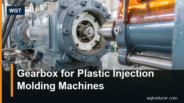
Gearbox for Injection Molding Machines | WGT
An injection molding machine carries two gearbox duties that look similar on a general arrangement drawing and behave nothing alike. The plasticizing drive turns a screw against a barrel of molten polymer and is judged on torque at low speed; the clamping drive moves a heavy platen against a mould and is judged on thrust, speed and repeatability. Buying one unit for both jobs, or specifying either on motor power alone, is the most common selection error on these machines.
Two Drives, Two Different Duties
The plasticizing unit is a screw inside a heated barrel. Polymer granules arrive at the feed throat, are conveyed and compressed along the screw, melted by shear and barrel heat, and pushed ahead of the screw as a shot. The screw must turn slowly with high torque, and it must also be able to move axially to inject.
The clamping unit holds the mould closed against the injection pressure. It does not turn anything continuously; it closes fast, builds tonnage slowly, holds, then opens. Its gearbox, where one is fitted, sees many short cycles and a large static load.
| Duty | Motion | Speed | Torque character | Cycle |
|---|---|---|---|---|
| Plasticizing screw | Continuous rotation | 30–250 rpm | High, steady, rises with viscosity | Long, minutes |
| Injection (screw advance) | Linear via screw or ram | Fast | Peak at fill, then decay | Seconds |
| Clamping (toggle) | Rotary to linear | Moderate | High breakaway, high hold | Seconds, repeated |
| Ejector | Linear | Slow | Moderate, shock at strip | Seconds |
| Nozzle touch | Linear | Slow | Low | Each cycle |
The Plasticizing Drive Is a Torque Problem
Screw torque is what sizes the gearbox, and it is not a catalogue number. It comes from the polymer, the screw geometry and the back pressure the process needs.
A workable estimate uses the screw's specific torque figure, quoted by machine builders in N·m per unit of screw diameter, and multiplies by the process back pressure and the metering length. In practice builders work from a table of experience: a 45 mm screw running polypropylene at moderate back pressure needs roughly 3,000 to 5,000 N·m at the screw shaft, and the same screw running polycarbonate at high back pressure moves toward the top of that band or beyond it.
Two consequences follow.
- Motor power is a poor proxy for screw torque. A 30 kW motor at 1,500 rpm and a 30 kW motor at 2,000 rpm give very different torque at the same power, and the gearbox is asked for torque, not watts.
- The gearbox ratio is set by the screw speed band, not by the motor. A screw that runs 20 to 200 rpm from a four-pole motor needs a ratio around 7 to 70, which is a two-stage helical band, or a single stage with a larger frame.
Speed Range and the Constant-Torque Question
Most plasticizing drives are expected to hold torque across a speed range of five to ten to one. A fixed-ratio gearbox fed by a variable-frequency drive can do that, provided the motor is not allowed to run below its cooling capability and the gearbox is rated for continuous duty at the low end.
At the low end the lubricant pump, if one is fitted, may not deliver, and splash lubrication becomes unreliable. That is why units on plasticizing duty are usually specified with an oil pump or with a generous splash arrangement and a cooler, and why the mounting position matters more than the catalogue suggests.
Backlash Matters More Than on a Conveyor
A plasticizing screw is a metering device. Shot weight repeatability depends on how precisely the screw position corresponds to a volume of melt, and backlash between the gearbox output and the screw shaft appears directly as a shot-to-shot variation.
The effect is not large in absolute terms - twenty arcmin at the output of a two-stage unit is a fraction of a millimetre of screw travel through the thrust bearing arrangement - but on a tight-tolerance part it is visible. Two-stage builds are preferred over three-stage for this reason, and the coupling between output and screw should be a clamped or keyed fit rather than a loose spline.
Reverse rotation, used on some machines to decompress before mould opening, doubles the number of times the drive crosses its backlash. Where that is standard practice, a lower-backlash build earns its cost.
Duty Cycle Is Where Units Fail
An injection machine cycles every fifteen to sixty seconds, and each cycle loads the drive in a pattern that a general industrial rating does not describe. The plasticizing drive has the easier pattern: a long, steady run at constant torque. The clamping drive has the harder one: a short burst at high load, repeated thousands of times a day.
For the clamping side the load spectrum matters more than the average. A toggle mechanism multiplies motor torque into tonnage through a nonlinear geometry, and the peak occurs near the end of stroke, where the linkage is close to straight. That peak is what fatigues the output bearing and the output shaft, and a service factor chosen on average load will be too low.
The practical specification carries the peak torque, the number of cycles per hour, and the expected life in cycles. A gearbox rated for 10,000 hours of continuous running is not automatically rated for three million clamping cycles.
Mounting on the Injection Unit
Plasticizing drives are usually flange-mounted to the barrel support, with the output coupled to the screw through a thrust bearing that takes the injection force. The gearbox must not carry that axial load; it is the machine frame's job.
Three mounting details decide whether the installation survives:
- Flange flatness and pilot fit. A flange bolted to a fabricated bracket without a pilot will move under torque reversal, and the movement shows up as a leaking output seal within a season.
- Thermal separation. The barrel is hot and the gearbox is not. A heat shield, an air gap, or a cooling fan on the input side is normal practice; a unit bolted directly to a hot plate runs its oil at barrel temperature plus its own rise.
- Service access. Oil level plug, breather and drain must be reachable with the machine guarded. A drive that needs a guard removed for an oil check will not get one.
Choosing Between Two and Three Stages
For screw speeds above roughly 100 rpm and ratios under 25, a two-stage helical unit is the natural choice: fewer meshes, lower losses, lower backlash. Below that speed, or where the ratio must exceed 40, a three-stage build brings the frame size down and keeps the housing within the space the machine has.
The three-stage MC3PLSF04 is typical of the larger end, where a big screw needs torque that a two-stage unit could only deliver in a case too large for the barrel support. For smaller machines the two-stage band usually wins on backlash and efficiency.
A Selection Checklist
Before asking for a quotation, have these numbers ready.
- Screw diameter, length-to-diameter ratio, and compression ratio.
- Polymer family and the highest viscosity grade the machine will run.
- Maximum back pressure, in bar, and the screw speed band.
- Motor power, speed and whether a variable-frequency drive is used.
- Required output torque at the screw shaft, with the service factor.
- Axial space between motor and barrel support, and the flange pattern.
- Ambient temperature and whether the machine sits near a hot runner manifold.
- Cycles per hour, and whether reverse rotation is used.
With those, the frame follows from torque and service factor, the ratio follows from the speed band, and the options follow from the environment. Anything less turns the selection into a guess that is validated on the shop floor.
Our engineers will size the plasticizing drive from the screw data, confirm the duty class in writing and quote the mounting arrangement alongside the unit. Run the numbers through the online selection system first and send the result with your enquiry.
Frequently Asked Questions
Can a general industrial gearbox be used on a plasticizing drive?
Yes, provided it is rated for the continuous torque at the lowest speed in the band and the mounting handles the heat. A general unit with an oil pump or splash cooling and a heat shield is common practice on mid-size machines.
Why do some machines use a hydraulic motor instead of an electric drive?
Hydraulic drives give high torque in a small package and tolerate stalling. Electric drives with a variable-frequency control are more efficient and quieter, and are now standard on all-electric machines, where the gearbox replaces the hydraulic motor entirely.
What service factor should be used for clamping drives?
At least 1.5 on the peak torque near end of stroke, and higher where the machine runs more than about 2,000 cycles per hour or the mould is heavy. The peak, not the average, is the number that sizes the output bearing.
How is screw torque measured in service?
From motor current and the known ratio, corrected for efficiency, or directly with a torque transducer in the coupling during commissioning. A baseline reading taken when the machine is new is the most useful maintenance tool on the drive.
Does gearbox backlash affect part weight?
Only where the machine meters by screw position rather than by volume. On position-metered machines a tighter mesh improves repeatability; on machines with a melt-pressure sensor the effect is largely absorbed by the control loop.