


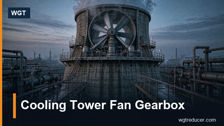
Cooling Tower Fan Gearbox: Wet Air Duty Selection | WGT
A cooling tower fan drive is specified by four things that rarely appear together on a normal fan: a very slow output speed, a vertical right-angle layout, an atmosphere that is at or near saturation, and a driven inertia several times the motor's. Get those four right and the gearbox runs for a decade on oil changes. Get the wet-air protection or the thrust interface wrong and the unit fails in two or three seasons, usually just after the warranty.
This note covers what makes the duty different, how the unit is normally built, and what to put in the enquiry so the supplier cannot quote a general-purpose unit that will not survive the plume.
Why a Cooling Tower Drive Is Not a Normal Fan Drive
Start with speed. Induced-draft tower fans are large - 6 to 12 m diameter is ordinary - and they turn slowly, typically 90 to 180 rpm, because tip speed limits both noise and the mechanical load on the blades. A 4-pole motor at 1475 rpm therefore needs a ratio of roughly 9:1 to 16:1, and the output shaft points vertically upward into the fan hub, with the motor sitting horizontally on top of the unit.
Then add the environment. The gearbox sits under the fan stack, in air that is saturated for most of the year and carries drift from the water. It sees the treatment chemicals in that water - chlorine, biocides, scale inhibitors - as an aerosol. It is inspected rarely, because getting to it means shutting down the cell and climbing. And it is expected to run 8000 hours a year in continuous duty.
That combination - slow, vertical, wet, unattended - is why a cooling tower gearbox is a distinct product rather than a catalogue fan drive with a coat of paint.
Fan Speed, Ratio and the Two-Stage Right-Angle Build
The standard arrangement is a two-stage bevel-helical unit: a bevel pair turns the drive through 90 degrees, a helical pair finishes the reduction, and the output is a hollow shaft or a flanged vertical shaft that the fan hub mounts onto directly. Two stages cover the 9:1 to 16:1 band comfortably; a third stage only appears when a slower fan or a 6-pole motor pushes the ratio past about 25:1.
The right-angle geometry is not a convenience, it is what allows the motor to sit horizontally above the stack where it can be serviced and where the cable entry stays out of the water. The bevel stage costs efficiency - roughly 1 to 1.5 % more than an equivalent helical pair - and that is accepted because the alternative layouts are worse.
Two details decide whether the unit behaves. The first is the oil system: a vertical-shaft unit does not splash oil the way a horizontal one does, so most tower drives use a shaft-driven or motor-driven pump to feed the upper bearings, with a return path that must work at low speed. A unit that relies on splash at 120 rpm will starve the upper bearing. The second is the output bearing arrangement, which brings us to thrust.
Thrust Loads and the Fan Hub Interface
The fan assembly hangs on the gearbox output shaft. A 9 m fan with hub and blades can weigh well over a tonne, and on top of that weight the aerodynamic thrust pushes down during operation. In most tower drives the gearbox output bearing carries that axial load directly, which means the axial rating is not a footnote in the selection - it is a primary sizing input.
State the fan assembly weight and the calculated thrust in the enquiry, and say explicitly whether the fan has its own thrust bearing or hangs on the gear unit. Suppliers design these two cases differently, and a unit specified for the wrong one will show up as bearing failure at 12 to 18 months, usually with the blame going to the oil.
The hub interface matters for the same reason. Hollow-shaft units with a shrink disc are the common choice because they transmit torque without a keyway and allow the hub to be positioned axially; taper bush arrangements are used on smaller fans. Whichever is used, the fit has to be checked on assembly - a hub that is not fully seated on the taper will move, and a moving hub destroys both the shaft and the fan balance.
The Wet Air Problem: Corrosion, Paint and Sealing
Wet air attacks three different things, and they need three different answers.
The housing exterior sees permanent humidity plus chemical aerosol. This is a corrosion-protection specification, not a paint colour: ISO 12944 category C4 or C5-M is the normal requirement for tower duty, delivered as a multi-coat epoxy system in the 240 to 320 µm dry-film range, with stainless or hot-dip galvanised fasteners. Standard workshop paint at 80 µm will fail in the first two years, starting at the fasteners and the shaft seal area.
The seals see water on the outside and oil on the inside, and they see chemical attack. Nitrile seals are adequate for clean water; where chlorination or biocide dosing is aggressive, FKM seals and a protected seal area are worth specifying. The output shaft seal is the vulnerable one because it faces upward into the plume and any water that pools on the hub runs toward it.
The breather is the quiet failure point. A standard breather draws moist air in and out with every temperature cycle, and that moisture condenses inside the housing. Tower drives are normally fitted with a desiccant breather, a closed-loop breather, or an expansion bladder, and the oil is checked for water content at every service. Emulsified oil in a tower gearbox almost always traces back to the breather, not to the seals.
| Item | Common tower specification | Why it matters |
|---|---|---|
| Housing protection | ISO 12944 C4 / C5-M, epoxy 240-320 µm | Permanent humidity plus chemical aerosol |
| Fasteners | A2 or A4 stainless, or hot-dip galvanised | First place paint breaks down |
| Shaft seals | FKM where biocide dosing is aggressive | Chemical attack at the output seal |
| Breather | Desiccant or closed-loop | Stops breathing in saturated air |
| Motor protection | IP55 minimum, IP66 where drift reaches the motor | Drift and washdown |
| Oil | ISO VG 220 or 320, or synthetic for cold climate | Low speed needs film thickness |
| Oil heater | Fitted below about 5 °C ambient | Cold starts at low speed |
| Backstop | Considered on multi-cell towers | Windmilling drives the unit backwards |
Starting a High-Inertia Fan Within Thermal Limits
A large fan is a high-inertia load, and the motor has to accelerate it. The gear unit sees that acceleration as heat in the bevel and helical meshes, and its thermal capacity during the start is a separate limit from its running thermal rating.
Three practical points. First, tell the supplier the fan inertia (or the fan diameter and mass) and the expected start time, so the start can be checked rather than assumed. Second, if the tower is started and stopped often - a common pattern on multi-cell installations following load - the accumulated starting duty has to be part of the thermal calculation, not an afterthought. Third, where a variable frequency drive is used, the ramp should be long enough to keep motor current within limits but not so long that the fan sits in a low-speed range with poor oil distribution; a 30 to 60 second ramp is a normal starting point for large cells.
One further point that catches people out: on multi-cell towers, a fan in a stopped cell will windmill in the airflow from its neighbours, driving the gearbox backwards through the output shaft. If the lubrication system depends on shaft direction, or if the motor cannot tolerate being back-driven, a backstop is specified. It is a cheap option at the order stage and an expensive retrofit.
Oil, Level and Cold Starts
Oil service in a tower drive is not complicated, but it is specific. Use the viscosity the manufacturer specifies for the actual sump temperature, not the viscosity on the data sheet of whatever oil is in the store. ISO VG 220 is common in temperate climates, VG 320 in hot climates, and synthetics where ambient falls below zero and a heater is not wanted.
Check the level at the sight glass with the unit stopped and the oil settled, and treat a rising level as a warning rather than a convenience - on a vertical unit it usually means water ingress, not overfilling. Change the oil after the first 500 hours, then at the interval in the manual - typically 5000 to 8000 hours or annually, whichever comes first, and always after any overheating event.
Between-Season Inspection
The annual shutdown is the only chance to look at the unit, so use it. Check the oil for water and metal. Inspect the output shaft seal and the hub fit for fretting. Look at the paint at the fasteners and the shaft area, which is where corrosion announces itself first. Record vibration on the output bearing as a baseline, and compare year on year rather than against an absolute limit - the trend is the useful signal. Confirm the breather is dry and the desiccant still active.
Most tower gearbox failures that reach the repair shop are not gear failures. They are water in the oil, a loose hub, or a starved upper bearing, and all three are visible at inspection long before they are audible in the plant.
To see how a right-angle hollow-shaft unit is presented with its thrust rating and ratio data, look at the MC3RLHT right-angle hollow-shaft gear unit. To size a tower drive against your fan speed, motor and thrust, enter the duty into the online selection system and send the resulting frame together with the fan weight and the corrosion class.
Frequently Asked Questions
What ratio does a cooling tower fan gearbox normally have?
Most tower drives fall between 9:1 and 16:1, matching a 4-pole motor at about 1475 rpm to a fan turning 90 to 180 rpm. Ratios up to about 25:1 are still handled in two stages; slower fans or 6-pole motors may need a third stage or a larger bevel pair.
Can a standard industrial gearbox be used on a cooling tower?
Mechanically it may carry the torque, but it usually fails on three counts: paint system, breather arrangement and output bearing thrust capacity. A standard unit is rated for its own weight on the shaft, not for a fan hanging on it in saturated air.
Why does water appear in the oil?
Almost always through the breather, as moist air is drawn in on cooling and condenses inside the housing. Desiccant or closed-loop breathers solve it. A failed output seal is the second cause, usually visible as oil weeping onto the fan hub.
How often should the oil be changed?
After the first 500 hours, then every 5000 to 8000 hours or annually, whichever comes first, and immediately after any over-temperature event. Check for water at every change - emulsified oil loses its film strength at exactly the low speeds these units run.
Should the fan be started with a VFD?
Usually yes on large cells, because it limits the starting current and reduces shock to the gear train. The ramp should be long enough to control current but short enough to avoid prolonged low-speed running with poor oil distribution; 30 to 60 seconds suits most tower fans.
