


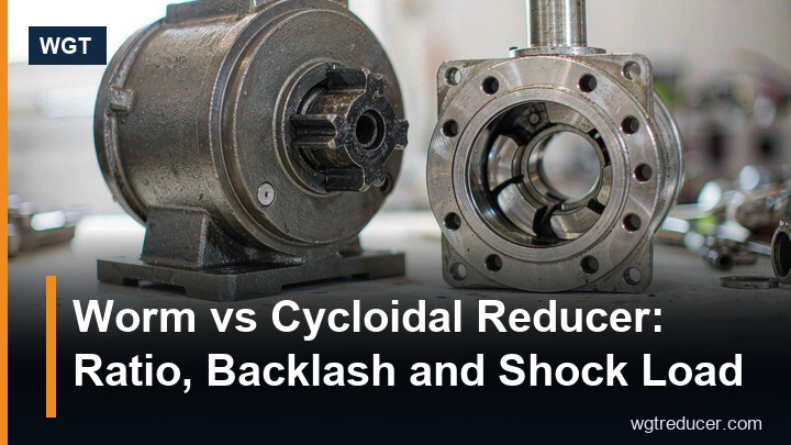
Worm vs Cycloidal Reducer: Ratio, Backlash and Shock Load
The short answer first: choose a worm gear reducer when the duty needs deep single-stage ratios, quiet running, a right-angle envelope and an intermittent cycle; choose a cycloidal reducer when the duty needs high shock resistance, low backlash and long continuous torque. Both reach similar ratio numbers on paper - a worm stage typically covers 5:1 to 100:1 in one pass, and a cycloidal stage typically steps through 6:1 to 87:1 - but the two mechanisms arrive at those ratios by completely different physics, and almost every practical difference between them follows from that one fact.
This comparison walks through the numbers a buyer actually argues about: how deep the ratios go, how much play the output has, what each mechanism does when a load slams into it, where the heat comes from, and which duty cycles each one prefers. By the end, the choice usually makes itself.
Two Mechanisms, Two Philosophies
A worm reducer transmits torque by sliding contact: a screw-shaped worm threads against a toothed wheel, and the ratio equals the number of wheel teeth divided by the worm's starts. One sliding mesh does all the work, which is why a single stage can reach ratios that helical stages need two or three steps to achieve - and why the mesh runs quietly and can even approach self-locking at the deep end.
A cycloidal reducer works by rolling, not sliding. An eccentric bearing carries a lobed cycloidal disc inside a ring of pins; the disc's lobes engage the pins one after another, so many contacts share the load at any instant. The eccentric motion, not a thread, generates the speed reduction - typically through ratios of 6:1, 11:1, 17:1, 23:1, 29:1, 35:1, 43:1, 59:1, 71:1 and 87:1 in a single stage, with two-stage builds reaching far deeper.
That single distinction - sliding mesh versus many rolling contacts - explains the columns in the table below.
The Numbers Side by Side
| Property | Worm gear reducer | Cycloidal reducer |
|---|---|---|
| Single-stage ratio range | 5:1 to 100:1 (continuous) | 6:1 to 87:1 (stepped values) |
| Mesh type | Sliding contact on the worm flank | Rolling contact across many pins |
| Typical efficiency | Falls with ratio - roughly 90% at shallow ratios down toward 40-50% at the deep end | Roughly constant across the range, commonly quoted at 75-90%+ |
| Backlash | Moderate to high; grows with wear | Low by construction; loads shared across pins |
| Shock load tolerance | Limited at deep ratios - the sliding flank is the weak point | High - shock spread across many simultaneous contacts |
| Self-locking tendency | Possible at high ratios with low lead angle | Not self-locking; needs a separate brake or holdback |
| Mounting envelope | Compact right angle; input and output at 90 degrees | Inline concentric; input and output share an axis |
| Heat behaviour | Heat concentrated in one sliding mesh | Heat spread around the eccentric mechanism at speed |
| Best duty | Intermittent starts and stops, low to mid torque | Continuous running, frequent shock, positioning duty |
Neither column is "better". Each is a different answer to the question of where the load paths and the losses should live.
Ratio Depth: Where Each Mechanism Stops
On ratio alone the two overlap heavily in the mid-range. Below about 10:1 both are comfortable; between 10:1 and 60:1 both are at home; past that, the characters diverge. A worm stage can still deliver 80:1 or 100:1 in one pass, but every extra point of ratio steepens the helix angle on the worm and drops the efficiency of that same sliding mesh - the deep end of a worm range is where the heat figure, not the torque figure, usually sizes the unit.
A cycloidal stage tops out near 87:1, and its ratio ladder is stepped rather than continuous - you take the nearest available pin configuration. What the cycloidal stage does not do is punish you for taking the deeper ratio: because its contacts roll, the efficiency curve stays comparatively flat across the ladder. When a duty needs 60:1 and continuous running, that flatness is often the deciding argument; when it needs 40:1 for eight hours a day, the worm's right-angle envelope and lower first cost usually win the room.
A practical note for mixed duties: these two mechanisms are not rivals so much as neighbours on a decision tree. Our NMRV worm gear series covers the intermittent, right-angle duties, while the X/B series cycloidal units cover the continuous, shock-hungry ones - and plenty of plants run both in the same hall.
Backlash and What the Output Does Between Moves
Backlash is where the two mechanisms feel furthest apart. In a worm mesh, the sliding flank needs running clearance by design, and the clearance migrates as the flank wears - a worm reducer that starts with modest play will typically measure more after its first season of starts. For a conveyor or an agitator this is irrelevant; for an indexer, a packaging cam or any position-holding axis it is the whole conversation.
A cycloidal drive's construction holds backlash low by geometry: the disc engages many pins at once, errors average across the contacts, and there is no single flank to wear one-sidedly. Industrial-grade cycloidal units hold their play within tight limits for years, which is why they appear under positioning axes and reciprocating machines despite costing more per newton-metre than a worm of the same ratio.
One caution cuts the other way. A worm's friction is sometimes a feature: at deep ratios with a low lead angle, the mesh resists back-driving, holding a stopped load between motor commands. A cycloidal drive transmits back-driving freely - it is closer to a stiff helical stage in that respect - so any load that can fall, run back or overtake its motor needs a brake or a holdback in the train, and that component belongs in the budget from the first quotation.
Shock Load: The Flank Versus the Crowd
Shock behaviour is the clearest physical argument between the two. A worm mesh concentrates contact on a narrow flank; a jammed apron feeder or a dropped load arrives at that flank as a spike, and at deep ratios the sliding contact has little margin to spare. Worm reducers survive shock duties, but they do it by being oversized - the service factor buys the margin the geometry lacks.
A cycloidal disc spreads every shock across all of its simultaneous pin contacts. A load spike that lands on one flank in a worm mesh lands on a crowd of pins in the cycloidal one, and none of them sees the full event. That is the mechanical reason vibratory feeders, bucket elevators, crushers' auxiliaries and other duty classes with hard starts gravitate to cycloidal builds even when a worm of equal ratio would cost less on the quotation.
Heat is the mirror image of the same story. A worm's losses concentrate in one sliding mesh, so its temperature rises with ratio and with duty cycle - a deep-ratio worm under continuous running needs its thermal rating checked as seriously as its mechanical one. A cycloidal's losses come from the eccentric mechanism and grow mainly with input speed, which is why cycloidal units prefer being driven at moderate speeds and why very fast inputs push them toward two-stage arrangements instead.
Maintenance and the Wear Story
Both mechanisms are mechanically simple, but they wear in different places. A worm reducer's wear item is the mesh itself: flank wear shows as growing backlash and, eventually, as oil debris in the sample. The oil programme is the worm's health monitor - sliding contact makes the oil do real work, so grade, level and change interval deserve the calendar discipline they get in any serious plant.
A cycloidal unit's wear items are the pins, the disc's lobes and the eccentric bearing - all rolling elements, all long-lived under clean oil, and all inspectable indirectly through vibration and temperature trends. Because its contacts roll rather than slide, a cycloidal drive is more forgiving of a stretched oil interval than a worm is, though "more forgiving" is not "immune"; the sample programme still catches water and wear metals months before either becomes a teardown.
Spares logic differs too. A worm reducer is defined by its ratio and frame, and the mesh is not a service part - a worn worm set usually means a new unit, which keeps the spare-parts shelf simple but the replacement decision large. A cycloidal drive's pin set and bearings are discrete components, so plants that standardise on a frame can hold pin kits and refresh the unit in place across long campaigns.
Which Reducer for Which Job
The choice compresses into four questions. Is the duty intermittent or continuous? Does the load shock, jam or stall? Does the axis hold position between moves? And does the layout want a right angle or an inline axis? Four "intermittent, gentle, loose, right-angle" answers point to a worm reducer; four "continuous, shocking, precise, inline" answers point to a cycloidal one. Most real duties land between, and the tie-breakers are usually thermal rating on the worm side and backlash plus shock margin on the cycloidal side.
| Duty profile | Better fit | Why |
|---|---|---|
| Gate, valve and dosing drives, short cycles | Worm | Right-angle envelope, quiet, low duty cycle |
| Screw conveyors and stirrers, moderate shock | Worm, sized with service factor | Deep ratio in one pass, low first cost |
| Vibratory feeders and elevator heads | Cycloidal | Shock shared across pins, survives hard starts |
| Indexing and positioning axes | Cycloidal | Low, stable backlash over years |
| Deep ratio with continuous running | Cycloidal (or two-stage helical) | Efficiency stays flat at depth |
| Load that can run back or fall | Worm, or add a brake/holdback | Possible self-locking; cycloidal needs a brake |
FAQ
Which one runs quieter?
The worm, in most cases. A sliding mesh in oil is inherently smooth, and at low output speeds a worm reducer often disappears into the hall's background noise. A cycloidal unit at high input speed carries a slight high-frequency signature from the eccentric mechanism; at moderate speeds the difference narrows considerably.
Can a cycloidal unit drop into a worm reducer's position?
Rarely without changes. The envelope differs fundamentally - right angle versus inline - so the swap usually involves a new mounting arrangement and, if the load can back-drive, a brake or holdback the worm never needed. Treat it as a layout decision, not a bolt-for-bolt exchange.
Why does my deep-ratio worm run hot, and is it a fault?
Heat is the price of the sliding mesh at depth: efficiency falls as the ratio rises, and the lost power becomes oil temperature. It is only a fault when the case temperature exceeds the unit's continuous thermal rating or climbs beyond its own trend line - which is exactly what the monthly reading and the oil sample exist to catch.
How much backlash is acceptable?
It depends entirely on the axis. A conveyor or an agitator tolerates whatever the mechanism provides. A positioning axis needs the play quantified and held - and that requirement, stated in the enquiry, is usually the argument that selects the cycloidal build over the worm.
Is the worm's self-locking a substitute for a brake?
Never design on that assumption. Self-locking tendency depends on ratio, lead angle and friction conditions, and it degrades with vibration, wear and temperature. Any load with stored energy - an inclined belt, a suspended gate, a vertical screw - gets a rated holding device regardless of which reducer is in the train.
Bring Us the Duty, Not Just the Ratio
Whether the answer lands on a worm stage or a cycloidal one, the selection argument is the same three numbers plus the duty class: motor speed, target output speed, required torque, and the shock profile the load delivers. Send those through our online selection system for a first-pass frame, or bring the duty description to us directly and we will confirm the ratio, the service factor and the thermal position in writing - including the brake or holdback question, which is the one buyers most often leave out.
