


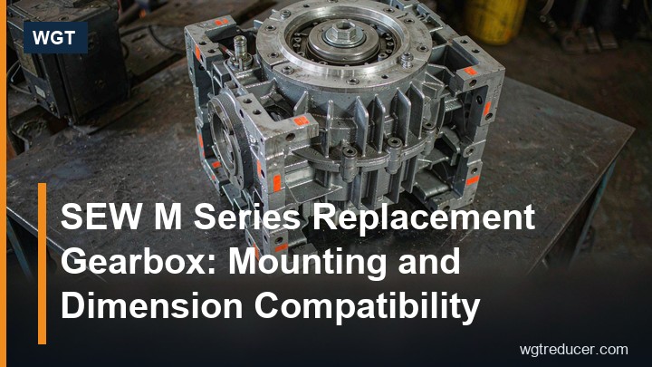
SEW M Series Replacement Gearbox: Mounting and Dimension Compatibility
Plants rarely remove an industrial gear unit because it failed to be a good gearbox. They remove it because a shaft snapped, a housing cracked, or the duty outgrew the frame - and then the clock starts. Every day the machine is down costs more than the drive itself, which is why the practical question is not "which gearbox is best" but "which unit can I bolt onto the existing foundation this week". That is the case for a dimension-compatible SEW replacement gearbox in the M series family: a unit built to the same mounting philosophy and interface dimensions as the drive it takes the place of, so the foundation, the coupling and the guard all stay as they are.
This article walks through what "dimension compatible" actually has to mean on a heavy industrial frame, which measurements to take before you order, and where interchange usually breaks down in the field.
Why Interface Dimensions Decide the Retrofit
An industrial gear unit touches the rest of the plant in four places: its feet, its input, its output and its torque path. Compatibility is only real when all four line up.
Feet. The bolt-hole pattern, the shaft height above the base and the foot thickness define whether the unit drops onto the existing foundation plate. A two-millimetre difference in shaft height can be shimmed; a twenty-millimetre difference usually cannot.
Input. Motor-mounted builds share the motor flange and shaft; coupled builds share the input shaft diameter, keyway and distance from the mounting face. If the input changes, the motor repositioning eats the space you may not have.
Output. A solid shaft must match diameter, keyway and the length available for the coupling. A hollow shaft must match the bore, the keyway or shrink-disc seat, and the length of the machine shaft that passes through it.
Torque path. On torque-arm builds the reaction arm length and pivot pin diameter define the mounting geometry. Get those wrong and the arm no longer reaches its bracket.
A serious supplier answers these points from a drawing before quoting, not after the unit arrives. The M-series catalogue and per-frame outline drawings exist exactly for this check, and WGT sends them as PDFs at the enquiry stage.
The M Series Naming System, Decoded
The designation encodes everything an interchange check needs, so it is worth reading carefully. The system follows the widely used industrial convention:
| Code element | Meaning | Interchange relevance |
|---|---|---|
| M2 / M3 / M4 / M5 | Industrial gear unit with 2 to 5 gear stages | Stage count sets the ratio band; a 3-stage unit covers the band most conveyors and mills need |
| P / R | P = all-helical parallel-shaft; R = bevel-helical right-angle | Must match, or the motor lands 90 degrees away from where it did |
| S / H | S = solid low-speed shaft; H = hollow shaft (keyed or shrink disc) | Defines the output connection to the machine |
| F / T | F = foot mounting; T = torque arm | Defines how the unit is held and how torque is reacted |
| V | Vertical build | Vertical frames follow their own size ladder (10-90) |
| 50-90 | Horizontal frame size | The number that ties foot pattern and shaft height to a dimension sheet |
So an M3PSF50 is a three-stage parallel-shaft unit with a solid shaft on feet at size 50, and the same housing ordered as M3PHF50 - you can see the exact build on the M3PHF60 hollow-shaft gear unit page - turns the output into a bore that slides over the machine shaft instead of driving through a coupling. Both are correct answers to the same duty; only the installation differs.
What to Measure Before Ordering
Field measurement beats catalogue memory every time. For a horizontal foot-mounted frame, take these seven:
- Shaft height from the base plate to the underside of the output shaft.
- Foot pattern - hole centres in both directions and the hole diameter.
- Output shaft diameter, keyway width and depth, and the exposed length.
- Bore data for hollow-shaft builds: bore diameter, keyway, shrink-disc seat width.
- Input geometry: flange diameter and spigot for motor builds, or the input shaft details for coupled builds.
- Overall length and width including the motor, to confirm the guard and walkway still fit.
- Rotation direction and shaft positions seen from the output end - easy to miss, expensive to fix.
Photograph the nameplate too. Even a worn plate usually reveals the frame size and the ratio, and both are enough to start the cross-check.
Where Interchange Typically Breaks
Three failure modes account for most of the trouble.
Stage-count mismatch. A buyer orders a two-stage unit for the same ratio without checking the torque rating at that ratio. More stages mean more torque capacity at a given ratio; a two-stage unit at i=90 will be undersized or thermally hopeless.
Hollow-bore details. The bore diameter matches but the shrink-disc seat is a different width, or the keyway is metric versus inch. The unit arrives, slides most of the way on, and stops.
Torque-arm geometry. The arm fits the pin but reacts through a different arc, so the belt tension or the tracking changes. On conveyor drives this shows up as persistent misalignment within weeks.
All three are caught by the drawing check in the previous section - which is why the check is not optional.
Ratio, Torque and the Duty Point
Compatibility is physical as well as geometric. The unit must carry the same duty, and the duty is three numbers: motor power and speed, required output speed, and the driven machine's load profile. The ratio follows from the speeds; the frame follows from the torque after the service factor is applied.
If you want the arithmetic done for you, the online gear reducer selection system takes motor speed, target output speed and machine type, and returns candidate frames with the ratio and service factor already checked. The same inputs let our engineers confirm a frame from the outline drawing and quote it in writing.
A worked example: a 55 kW motor at 1480 r/min drives a belt conveyor head pulley at 31 r/min. The ratio is 1480 / 31 = 47.7, so a ratio near 48 is selected. With the service factor for a uniform conveyor load applied, a size 50 three-stage frame carries that duty continuously - which is why the M3PSF50 industrial helical gear unit is a common answer for exactly this class of drive.
The M3 Family at WGT: Frames and Builds
WGT supplies the horizontal M3 family from size 50 to 90 in the P and R layouts, with solid and hollow outputs and foot or torque-arm mounting. The frames currently documented on the site give a feel for the range:
| Model | Layout | Output | Typical duty |
|---|---|---|---|
| M3PSF50-M3PSF90 | Parallel shaft, 3-stage | Solid, foot mounted | Conveyors, mills, shredders |
| M3PHF50 / M3PHF60 | Parallel shaft, 3-stage | Hollow, foot mounted | Screw conveyors, rotary valves, mixers |
| M3RSF50 | Right angle, bevel-helical | Solid, foot mounted | Inclined conveyors, classifiers, chippers |
The family continues upward: M4 and M5 builds extend the ratio band for very high reductions, and vertical V builds cover machine shafts that rise through a floor. Each frame shares the same case-hardened, ground helical gearing and the horizontally split housing that heavy industry expects for inspection without disassembly.
How the Supply Route Works
Sourcing a dimension-compatible unit is mostly a documentation exercise done quickly. The route that works:
- Send the nameplate photo, the seven measurements, and a sentence about the driven machine.
- WGT returns the outline drawing for the matching frame and confirms the interface dimensions.
- The duty point is checked (ratio, torque, service factor) and a written quotation follows.
- The unit ships factory-tested in an export wooden crate, typically in five to ten weeks depending on the frame, with a one-year warranty.
Because the drawings are exchanged before the order, the moment of truth moves from the installation site to the email thread - which is exactly where a mismatch costs a reply instead of a shutdown.
Frequently Asked Questions
Do dimension-compatible units share the same internal parts as the original brand?
No, and they do not need to. Compatibility concerns the interfaces the plant touches: feet, shafts, bores, flanges and the torque path. Internally the gearing, bearings and lubrication follow the supplying manufacturer's own design. What matters for a retrofit is that nothing outside the housing has to change.
Can a parallel-shaft unit be substituted where a right-angle unit was installed?
Only if the plant has room for the motor to stand along the machine axis instead of beside it. The gearing can cover the duty either way, but the footprint rarely allows the swap on an existing installation - which is why the P/R letter in the code should be treated as fixed.
What documentation do you need to quote an interchange unit?
A nameplate photo, the shaft height and foot pattern, output shaft or bore details, the motor power and speed, and the required output speed. With those, the outline drawing check and the duty-point calculation are both possible in a single pass.
How is the one-year warranty handled on industrial frames?
The warranty covers manufacturing and material defects under rated duty, the same as for any industrial gear unit supplied new. Units are bench-tested before packing and the test record ships with the unit.
