


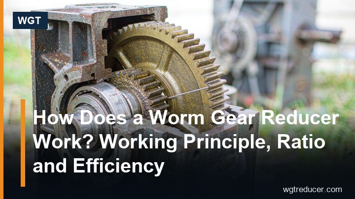
How Does a Worm Gear Reducer Work? Working Principle, Ratio and Efficiency
A worm gear reducer cuts motor speed in one compact 90-degree stage, and it is the only common reducer that can hold a load without a brake. It does this with a sliding mesh between a screw-shaped worm shaft and a bronze worm wheel, which is also the reason its efficiency is lower than a helical unit. This article walks through the geometry, how the ratio is set, where the efficiency goes, and how to tell whether a given unit will self-lock.
What a Worm Gear Reducer Actually Does
A worm gear reducer takes a fast, low-torque input from a motor and delivers a slow, high-torque output at 90 degrees to the input shaft. Unlike a helical or planetary reducer, the two shafts are not parallel and not in line: the worm shaft sits below or beside the worm wheel, and the wheel is driven by the helical thread of the worm.
That layout gives three practical properties engineers rely on:
- High ratio in a single stage. One worm pair can deliver ratios from 5:1 to 100:1 without adding stages.
- Compact 90-degree drive. No bevel pair is needed to turn the drive direction.
- Possible self-locking. Under the right lead angle, the worm cannot be back-driven by the load.
The Geometry: Worm Shaft and Worm Wheel
The worm is a hardened, ground steel screw with one or more starts of thread. The worm wheel is a bronze gear that meshes with that thread. Three numbers define the mesh:
| Term | What it means | Typical value |
|---|---|---|
| Starts (Z1) | Number of thread starts on the worm | 1, 2 or 4 |
| Wheel teeth (Z2) | Number of teeth on the bronze wheel | 20 to 80 |
| Lead angle (γ) | Angle of the thread relative to the wheel axis | 3° to 25° |
The worm and wheel are set at 90 degrees with the worm axis offset by the centre distance. That centre distance — not the motor frame — is usually the figure that decides whether a replacement unit will drop into an existing machine.
How the Ratio Is Set
The ratio of a single-stage worm reducer is simply the wheel tooth count divided by the number of worm starts.
Ratio = Z2 / Z1
That single formula explains every ratio you see on a nameplate:
| Worm starts (Z1) | Wheel teeth (Z2) | Resulting ratio | Typical duty |
|---|---|---|---|
| 1 | 40 | 40:1 | Conveyors, hoists, lifting |
| 2 | 40 | 20:1 | Mixers, agitators |
| 4 | 40 | 10:1 | Positioning, indexing |
| 1 | 80 | 80:1 | Slow feeders, gates |
A single-start worm gives the highest ratio and the strongest self-locking tendency. A four-start worm gives a lower ratio, higher efficiency and a faster output — but it will not hold a load on its own.
Sliding Contact and Where the Efficiency Goes
In a helical or bevel pair the teeth roll against each other. In a worm pair the threads slide, and sliding friction converts a large share of the input power into heat rather than output torque. That is why a worm reducer runs hotter than a helical unit of the same rating.
Efficiency depends mainly on the lead angle and the lubrication:
| Lead angle | Self-locking | Typical efficiency |
|---|---|---|
| Below 5° | Yes | 40% – 60% |
| 5° – 10° | Marginal | 60% – 75% |
| Above 15° | No | 75% – 90% |
Two consequences follow. First, when you select a worm unit for continuous duty you must check the thermal rating, not just the mechanical torque rating — the gearbox may be able to transmit the torque but unable to shed the heat. Second, a worm reducer is normally the wrong choice for a high-power, continuously running drive; a helical or helical-bevel unit will use less energy over the year.
Self-Locking: When It Holds and When It Doesn't
Self-locking means the load cannot drive the worm backwards. It is the property that lets a worm reducer hold a raised load without a brake, and it is the single most over-promised feature in gearbox sales.
The rule of thumb is that self-locking appears when the lead angle is smaller than the friction angle of the worm-and-wheel pair — in practice, at lead angles below roughly 5 degrees, which usually means a single-start worm. Three cautions matter:
- Static self-locking is not dynamic self-locking. A unit that holds a static load may still be back-driven by vibration or by a shock load.
- Efficiency and self-locking pull in opposite directions. The lower the lead angle, the safer the lock and the worse the efficiency.
- Never rely on self-locking for safety-critical holding. Use a brake motor or a holdback device where a falling load is a hazard.
Heat, Lubrication and Duty
Because sliding friction dominates, lubrication is not optional maintenance — it is a design parameter. A worm reducer should use a gear oil with the correct viscosity grade and the correct additive package for bronze-on-steel contact, and the oil level and breather must be checked at the interval the manufacturer specifies.
Three practical checks keep a worm drive alive:
- Oil sump temperature should stay within the unit's rated range; sustained overheating is the usual first sign of an undersized selection.
- Mounting position must match the oil-level mark; the same unit has different sump levels for different mounting positions.
- Run-in period — worm pairs lap themselves in over the first hours and the oil should be changed after the initial running-in.
Worm vs Helical: A Quick Decision Table
| Criterion | Worm reducer | Helical reducer |
|---|---|---|
| Ratio per stage | 5:1 – 100:1 | 3:1 – 8:1 |
| Efficiency | 40% – 90% | 96% – 98% |
| Self-locking | Possible | No |
| Noise | Very low | Low |
| Heat generation | High | Low |
| Best for | High ratio, compact, intermittent duty | Continuous, high efficiency duty |
Pick a worm unit when you need a large ratio in one small 90-degree package, low noise, or a hold-without-brake behaviour on an intermittent duty. Pick a helical or helical-bevel unit when the drive runs continuously, when energy cost matters, or when the output torque is high enough that heat becomes the limiting factor.
Key Takeaways
- A worm reducer cuts speed with a sliding 90-degree mesh, which gives high ratios in one stage but lower efficiency than a rolling-gear reducer.
- The ratio is the wheel tooth count divided by the worm starts; one start gives the highest ratio and the strongest self-locking.
- Efficiency rises with lead angle and falls with it — and the lead angle that locks the drive is the same one that wastes power.
- Always check the thermal rating for continuous duty, not only the mechanical torque rating.
FAQ
What is the typical efficiency of a worm gear reducer?
Between roughly 40% and 90% depending on the lead angle and lubrication. Single-start worms with low lead angles sit near the bottom of that range; multi-start worms with high lead angles approach the top.
Will a worm gearbox hold a load without a brake?
Only if it self-locks, which normally requires a lead angle below about 5 degrees, usually a single-start worm. Self-locking is not guaranteed under vibration or shock, so safety-critical holding should use a brake.
What is the difference between a worm gear reducer and a helical gear reducer?
A worm reducer uses a sliding mesh at 90 degrees and delivers high ratios in one stage with lower efficiency. A helical reducer uses a rolling mesh, is more efficient and quieter at high speed, but needs more stages to reach the same ratio.
Can a worm gear reducer be mounted in any position?
The unit can usually be mounted in several positions, but each position has its own oil-level mark. Mounting in a position other than the one it was filled for will either starve the bearings or overfill the sump.
Need a Worm Reducer Sized for Your Duty?
Send us the input speed, the required output torque and the mounting position, and we will return the frame size, ratio and drawing the same day. If you prefer to work the numbers out yourself first, run your duty point through the WGT Motor & Gearbox Online Selection System — it covers motor power, ratio and mounting on one screen and gives you the model before you ask us.
