


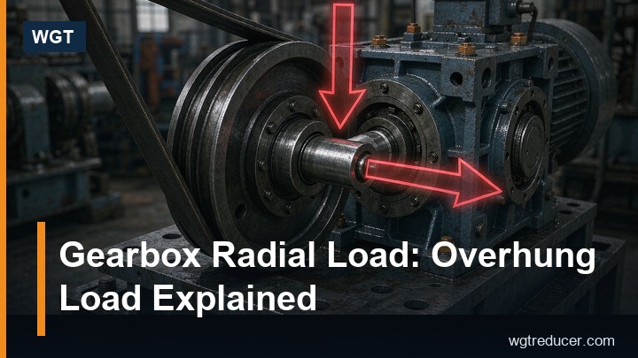
Gearbox Radial Load: Overhung Load Explained
A gearbox radial load is the side force applied to the output shaft by whatever is mounted on it - a pulley, a sprocket, a gear, or the weight of a coupled machine. It is separate from the torque rating and it is frequently the reason a correctly sized gearbox fails early. The torque tells you how much twisting the teeth must carry; the radial load tells you what the bearings and the shaft overhang must carry, and the two limits are reached at different points in the duty.
The axial load - thrust along the shaft axis - arrives from the same mountings and from the gear mesh inside the box. This guide covers how each one is generated, how to calculate the radial figure properly, why the distance from the housing changes everything, and which field checks reveal an overload before the bearings do.
Radial and Axial Loads in Plain Terms
Radial load acts at right angles to the shaft centreline. A belt pulling on a sheave, a chain pulling on a sprocket, the weight of a screw conveyor hanging on a coupling - all radial. The unit is newtons or kilonewtons, and its magnitude depends on torque and on the pitch diameter of whatever is mounted on the shaft.
Axial load acts along the centreline. It pushes the shaft into the housing or pulls it out. Sources are external - a thrust load from a screw or an agitator, the axial component of a helical gear set mounted on the shaft - and internal, from the reaction of the mesh inside the gearbox.
Every catalogue rating for a gearbox is only meaningful when both are stated together with the point of application. A rating of 12 kN radial at mid-shaft means exactly that: 12 kN, at that position, in that direction of rotation. Move the load outboard or reverse the rotation and the permissible figure changes.
Where the Load Comes From
The same transmitted torque produces very different radial loads depending on the drive element, because a belt needs tension to transmit power and that tension loads the shaft even at standstill.
| Drive element | Typical load factor K | Why |
|---|---|---|
| Spur or helical gear, direct mesh | 1.0 | Tooth force only, no pre-tension |
| Chain sprocket | 1.0–1.25 | Some catenary and pre-tension effect |
| Timing belt pulley | 1.25–1.5 | Pre-tension required for tooth engagement |
| V-belt sheave | 1.5–2.0 | Sum of tight and slack side tensions |
| Flat belt pulley | 2.0–2.5 | High pre-tension for friction drive |
| Coupled machine, no bending | 0 to small | Only residual misalignment forces |
Use the gearbox maker's own factor where one is published; the ranges above are the industry convention, not a substitute for the data sheet. The important point is that a V-belt drive roughly doubles the radial load compared with a gear of the same pitch diameter, and buyers who swap a gear coupling for a belt drive on an existing unit often cross the bearing limit without changing the torque at all.
Calculating the Overhung Load
The radial load from a torque-transmitting element is calculated from the torque and the effective radius:
F_r = (2 × T × 1000) / d × K
where F_r is the radial load in newtons, T is the torque at that shaft in newton-metres, d is the pitch diameter of the pulley, sprocket or gear in millimetres, and K is the load factor from the table above.
A worked example, using assumed numbers so you can substitute your own: output torque 1200 N·m on a 250 mm pitch diameter V-belt sheave, K = 1.5.
- 2 × 1200 × 1000 = 2,400,000
- divided by 250 = 9,600 N at K = 1.0
- multiplied by 1.5 = 14,400 N, or 14.4 kN
If the catalogue figure for that unit at mid-shaft is 12 kN, the application is already 20 percent over the limit before any service factor is applied, even though the torque may sit comfortably inside the torque rating. That single comparison explains a large share of premature output bearing failures in the field.
Distance From the Housing and the Four-Part Rating
A shaft is a cantilever. The bending moment at the bearing is the load multiplied by the distance from the bearing to the load point, so moving a pulley 40 mm further out along the shaft increases the moment in proportion and reduces the permissible load.
| Load position | Practical effect on allowable radial load |
|---|---|
| At the shaft shoulder, close to the housing | Highest permissible load; the catalogue figure is usually quoted here or at mid-shaft |
| Mid-shaft | The standard reference point for most published ratings |
| Near the shaft end | Markedly lower; check the maker's curve rather than assume |
| Extension piece or adapter fitted | Recalculate for the new distance; never carry the old figure across |
Two rules follow from this. First, always compare your calculated F_r with the rating at the actual load position, not with the headline figure. Second, anything that lengthens the overhang - a spacer, a taper bush adapter, a repaired shaft with a sleeve - needs the calculation repeated. A belt that was acceptable at mid-shaft can be out of limits at the end of the shaft with no change to the machine duty.
Axial Load: Thrust From Inside and Outside
Axial load arrives from two directions, and both have to be accounted for.
From the mesh inside the box. Helical gearing generates an axial component because the teeth are cut at an angle; the thrust is carried by the bearings and by the housing. Worm and bevel units also produce thrust at the mesh. This is designed in, and it is the reason a helical unit uses a bearing arrangement that can take thrust while a simple spur unit may not need one.
From outside. A screw conveyor with a pressured end, an agitator with a propeller pushing against a tank, a vertical shaft carrying its own weight, a machine coupled through a limited-end-float coupling that bottoms out. External thrust is the one that gets missed, because it usually appears as a line item in someone else's specification rather than on the gearbox drawing.
The practical checks: confirm the direction of the external thrust, confirm its magnitude at the worst operating point, and confirm that the coupling chosen can absorb end float without transferring it. A rigid coupling on a shaft that grows 1 mm with temperature rise will deliver that movement to the bearing as thrust.
Which brings the rating itself into focus. A useful rating statement has four parts, and a missing part is a question to ask rather than a gap to fill with an assumption:
- Magnitude - permissible radial load in kN, and permissible axial load in kN.
- Position - where on the shaft the radial figure applies.
- Direction - which sense of rotation and which side of the shaft; some units are rated differently for clockwise and counter-clockwise running because of how the internal thrust is reacted.
- Duty - whether the figure is continuous or intermittent, and whether a service factor has already been included.
When a machine is retrofitted, do the comparison against the duty the unit actually sees, not the duty it was ordered for. Belt tension creeping up over years, a bigger pulley fitted to gain speed, a heavier screw flight welded on site - all of these raise the radial load while the gearbox nameplate stays the same. Keeping the original selection sheet with the unit is worth more than any after-the-fact estimate.
How Overload Turns Into Bearing Hours
Bearing life is not linear in load. For a roller bearing the rating life follows:
L10 = (C / P)^(10/3) × 10^6 revolutions
where C is the basic dynamic load rating and P is the equivalent dynamic bearing load, which includes the radial and axial components weighted by the bearing's X and Y factors. A ball bearing uses an exponent of 3 instead of 10/3.
The exponent is what makes the consequences severe:
| Load relative to rating | Relative life, roller bearing | Relative life, ball bearing |
|---|---|---|
| 1.0 × P | 1.0 | 1.0 |
| 1.25 × P | about 0.47 | about 0.51 |
| 1.5 × P | about 0.28 | about 0.30 |
| 2.0 × P | about 0.09 | about 0.125 |
A 25 percent radial overload roughly halves the life; double the load and you keep about a tenth of it. This is why a unit that is "only a little over" fails in months rather than years, and why the calculation is worth doing before the order rather than after the warranty claim.
Hollow Shaft and Shaft-Mounted Units
Shaft-mounted and hollow-shaft gearboxes carry radial load in a different way. The unit is mounted directly on the driven shaft, so the load path runs through the hollow bore rather than through an output shaft and coupling. A torque arm reacts the housing against rotation, and its reaction force is added to the loads the bearings see.
Three points decide whether such an installation lasts. The torque arm must be mounted so that its reaction is taken by a structure, not by the machine frame's sheet metal. The shrink disc or keyless clamping ring must be tightened to the specified torque, because slip under load frets the shaft and destroys the fit. And the axial location must be fixed on one side only - a hollow shaft unit clamped at both ends of a shaft that grows with temperature will load its own bearings.
Our shaft mounted gearbox range is rated with these conditions stated, and the selection sheet carries the radial figure at mid-bore so the comparison above can be made directly.
Field Checks Before Blaming the Gearbox
When an output bearing fails early, the load path is usually visible on the machine before anything is opened.
- Belt tension - measure deflection against the belt maker's figure. Over-tensioned belts are the single most common cause of unexplained radial overload.
- Sprocket and pulley offset - a sheave set too far out on the shaft multiplies the bending moment without any change in tension.
- Wear pattern on the sprocket - uneven tooth wear points to misalignment, which adds an axial component.
- Coupling condition - worn elastomer elements or a bottomed-out limited-end-float coupling transfer loads the design never intended.
- Oil analysis - iron rising with copper or tin indicates a bearing cage or race breaking down rather than a gear problem.
- Temperature at the output bearing housing - a rise of 10 K over the historical baseline at the same ambient and load is worth investigating before it becomes a failure.
Measure the actual overhang and belt tension, recalculate F_r, and compare it with the rating at that position. In most early-failure cases the arithmetic answers the question in ten minutes.
FAQ
What is the difference between radial load and torque rating?
Torque is the twisting moment the gear teeth and shafts must transmit, rated in newton-metres. Radial load is a side force on the shaft, rated in kilonewtons and limited by bearing capacity and shaft bending. A gearbox can be well inside its torque rating and still be overloaded radially, because the two limits come from different components.
How do I calculate overhung load on a gearbox?
Multiply the torque in newton-metres by 2000, divide by the pitch diameter of the pulley, sprocket or gear in millimetres, then multiply by the load factor for that drive type. The result is the radial load in newtons. Compare it with the catalogue rating at the actual load position along the shaft, not the headline figure.
Does a V-belt cause more radial load than a gear coupling?
Yes, substantially. A gear coupling transmits torque with almost no side force, while a V-belt needs pre-tension to work, and that tension loads the shaft continuously. Typical load factors are about 1.0 for a gear mesh and 1.5 to 2.0 for a V-belt sheave, so the same torque can produce close to double the radial load.
Can a gearbox take axial load from a screw conveyor?
Only within the thrust rating of its bearing arrangement, and only in the direction that arrangement is designed for. A screw with a pressured end can develop substantial thrust, and a rigid coupling will pass all of it into the gearbox. State the thrust magnitude and direction when ordering, or isolate it with a thrust bearing on the machine side.
Why did my gearbox bearing fail when the torque was within rating?
Because bearing life depends on load raised to a power of roughly 3.3, so a modest radial overload cuts life sharply - a 25 percent overload roughly halves it. Common causes are over-tensioned belts, a pulley moved outboard on the shaft, a coupling bottoming out, or a retrofit that changed the drive element without recalculating the overhung load.
Send us the torque, the drive element and its pitch diameter, the overhang from the housing face, and any external thrust - our engineers will run the radial and axial check against the actual unit and confirm the bearing arrangement. For a first pass, the online selection system sizes the gearbox and reports the load case you are working to.
