


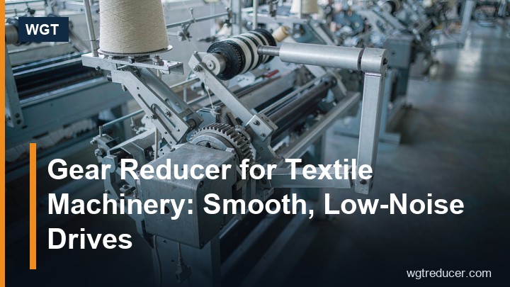
Gear Reducer for Textile Machinery: Smooth, Low-Noise Drives
A textile line rarely loads a gearbox the way a crusher or a conveyor does. The torques are moderate, but the drive runs around the clock, starts and reverses with the doffing cycle, and sits within a few metres of fabric that must not pick up oil mist or be shaken by vibration. Choosing a gear reducer for textile machinery is therefore less about peak torque and more about three quieter qualities: smooth torque transfer, low noise, and clean oil containment.
This article walks through what those qualities mean in gearbox terms, which families suit which positions on the line, and how to check a candidate frame before ordering.
Why Textile Drives Are Unforgiving in Small Ways
Spinning, winding and finishing machines run at constant or slowly changing speeds for weeks. Under that duty, any roughness in the gear mesh shows up as a periodic mark in the yarn or fabric, and any resonance shows up as noise complaints on the shop floor. Three failure modes dominate:
- Vibration transmitted into the frame, which the frame then passes to thread guides and rollers, producing barre or count variation.
- Oil mist or seepage near open fabric, which creates stains that no wash formula removes cheaply.
- Bearing wear from chronic misalignment, because many textile machines are built on long, slender frames that flex during cleaning and maintenance.
A reducer chosen for this environment needs ground or fine-finished gearing, a housing that stays dimensionally stable, and a seal concept that assumes the machine will be hosed down around it.
Noise: What Actually Makes a Gearbox Quiet
Noise in a gear unit comes mainly from tooth engagement error, not from power level. In practice, three choices decide the outcome:
- Helical versus spur gearing. Helical teeth engage progressively along the face width, so the mesh is far quieter than a spur mesh at the same torque. Every frame in the range used for textile work should be helical by default.
- Tooth quality and finish. Ground teeth keep the transmission error low across the whole ratio band, and they hold that quality for years because wear concentrates less on a correctly finished flank.
- Housing stiffness and mounting. A foot-mounted housing bolted to a stiff machine bed radiates less than a lightly ribbed housing cantilevered off a sheet-metal bracket. Where the drive sits near operators, mounting design matters as much as the gearbox itself.
Bevel-helical units are also acceptable near work areas, provided the bevel stage is a spiral-bevel and correctly lapped; a straight-bevel input is noticeably louder and is better avoided in spinning rooms.
Where Gearboxes Sit on a Textile Line
Different positions load the drive differently, and it pays to match the layout to the station:
| Line position | Typical duty | Suitable layout |
|---|---|---|
| Spindle and flyer drives | Constant speed, light torque, strict smoothness | Inline helical, hollow or solid shaft |
| Take-up and winder drives | Frequent starts, controlled tension | Inline helical with careful backlift control |
| Dyeing and finishing ranges | Humid, washdown, moderate torque | Sealed helical units, foot or shaft mount |
| Baling and waste handling | Shock loads, intermittent duty | Bevel-helical right-angle, solid shaft |
| Conveyor and material feed | Continuous, overhung load | Helical inline or parallel shaft |
The common thread is that most positions are served by standard industrial gear units once the noise and sealing requirements are written into the specification. Special textile-only gearboxes are rarely necessary at the torque levels involved.
Matching the Layout to the Machine Frame
Textile machines are long, and the drive usually sits at one end of a shaft line that runs the machine's length. Two mounting decisions follow from that geometry:
- Shaft-mounted hollow-bore units let the reducer slide straight onto the machine's long drive shaft, removing one coupling and its alignment work. A torque arm tied back to the frame carries the reaction, and the drive can be exchanged without touching shaft alignment.
- Foot-mounted solid-shaft units suit positions where the machine shaft already carries its own bearings and the reducer meets it through a coupling - take-up stands, baler feeders, finishing range drives with independent gearboxes.
Right-angle inputs earn their place where the floor plan is tight along the machine axis: turning the motor ninety degrees shortens the drive train and keeps motors clear of creel and doffing aisles.
Sealing and Oil Containment Near Fabric
This is the requirement most often under-specified. A gearbox beside open fabric needs:
- Seal choices rated for the duty, with lip seals or mechanical seals at the output where the shaft passes near product.
- Breather placement routed away from the fabric path, or a sealed-for-life concept on smaller frames, so warm oil vapour does not vent toward yarn.
- A defined leak-response plan: drip trays and inspection intervals written into the maintenance schedule, not improvised after the first stain appears.
Buyers should ask the supplier which seal options exist per frame and state the ambient - dye houses run hot and humid, and a seal specified for a dry spinning room may not be the right one there.
Sizing a Textile Drive Without Over-Motoring
Because torques are modest, the temptation is to pick an oversized frame "for safety". Oversizing hurts twice: it raises the noise floor (larger meshes running lightly loaded are often louder relative to their rating) and it wastes energy around the clock. A better sequence:
- Take the absorbed power at the driven shaft from the machine builder, not from motor nameplate, if the two differ.
- Compute the ratio from motor speed to working speed at the spindle, roller or conveyor.
- Apply the service factor that matches the duty class - frequent starting and reversing on winders justifies a higher factor than a steady conveyor.
- Check the overhung load at the output shaft, because many textile shafts carry pulleys and tension rollers close to the gearbox.
A compact parallel shaft or inline helical frame usually covers spinning and winder positions; heavier bevel-helical frames belong on baling and material handling ends of the plant.
A Worked Selection Example
Consider a take-up drive on a winding station: a 5.5 kW motor at 1440 rpm must turn the take-up roll shaft at 60 rpm, and the machine frame provides a driven shaft in its own bearings.
- Ratio: 1440 / 60 = 24, so a ratio near i=24 is selected from the catalogue band.
- With the service factor for frequent starts applied, a mid-size helical frame in the R series inline family covers the torque with margin - see the torque-arm and inline options on our M3RHT60 torque arm hollow shaft gearbox page for the shaft-mounted variant of the same idea.
- Because the roll shaft runs in its own pillow blocks here, a solid output with a flexible coupling would also be reasonable; the M3RSF60 right angle gear reducer shows the foot-mounted, solid-shaft alternative.
The same three numbers - motor speed, target output speed, required torque - decide the frame for any textile position; the sealing and mounting options are then selected per station. You can cross-check ratios and service factors in the online selection system before requesting a quotation.
Questions and Answers
How quiet can a standard industrial gearbox be in a spinning room?
A helical gear unit with ground teeth, correctly mounted on a stiff bed, runs quiet enough for positions near work areas. The dominant remaining noise is usually structure-borne, so mounting and coupling choices matter as much as the gearbox rating.
Should I specify synthetic oil for textile machines?
Synthetic oils widen the temperature band and extend change intervals, which reduces the number of oil handling events near product. Confirm the seal material is compatible before switching, and keep the breather routed away from fabric either way.
What protection grade do textile drives need?
For dry spinning and winding rooms, standard industrial sealing with a sound breather strategy is normally sufficient. Dyeing and finishing ranges with hose-down practice need sealed cable entries, protected shaft seals and drainage-conscious mounting.
Can one reducer serve both a winder and the feed conveyor behind it?
Sometimes, if the duty cycles and torques overlap, a common frame keeps spares simple. Check that the higher starting frequency of the winder is covered by the service factor before standardising.
How often should textile gearboxes be inspected?
A quarterly check of oil level, seal condition and mounting bolts fits most continuous textile duties; shorten the interval in hot, humid finishing areas or wherever oil stains on fabric have already occurred once.
Summary and Next Step
Textile machinery rewards drives chosen for smoothness and cleanliness rather than raw torque: helical gearing for quiet meshing, a mounting layout that matches the machine's long shaft line, and sealing specified for the actual ambient. Size from absorbed power and duty class, resist the urge to over-frame, and write the oil containment plan into the maintenance schedule before the first stain appears.
Send WGT your machine layout, motor data and target speeds, and we will return a frame selection with ratio, service factor and mounting options in writing - backed by outline drawings you can check against the machine before ordering.
