


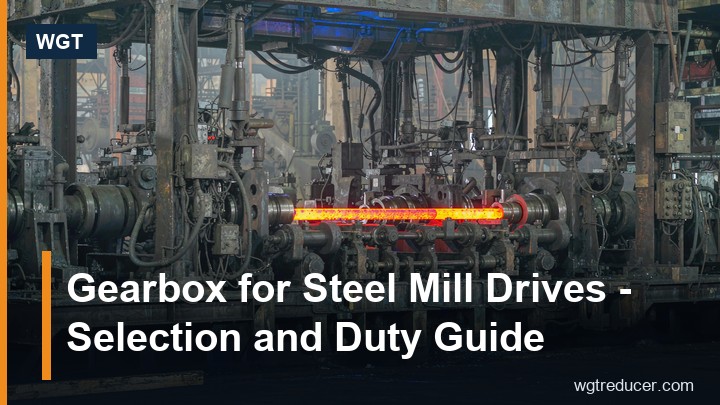
Gearbox for Steel Mill Drives - Selection and Duty Guide
A gearbox for steel mill service has one defining job: it must deliver steady reduction ratio under loads that are anything but steady. Mill drives see start-up against a loaded line, impact torques when material catches or slips, dust, heat and long continuous shifts, so the selection question is never just the ratio. This guide walks through the duty profile, the frame families that suit mill service, and the sizing checks that keep a drive alive between planned shutdowns.
What Makes Steel Mill Duty Different
Three features separate a steel mill from most other gearbox applications, and each one changes the sizing maths.
First, the load is shock-prone. A conveyor or feeder in a mill starts under load more often than not, and material bridging or a slipped slab produces torque spikes several times the running value. A unit sized only to the absorbed power will survive the calculation and fail the plant.
Second, the environment is hostile. Mill scale, ambient heat from process equipment, and dust that finds every breather all shorten oil and seal life. Thermal margin and simple, serviceable sealing matter as much as the catalogue torque column.
Third, availability is the whole point. In many mills the gearbox is on the critical path of the line: if it stops, everything behind it stops. That pushes selection toward frames with conservative ratings, standard spares and mounting layouts that allow a change-out without rebuilding the plinth.
The Duty Profile to Write Down
Before any frame is picked, write down six numbers. They are the same six any factory will ask for, and having them turns a week of back-and-forth into a single quotation.
| Item | What to record | Why it matters |
|---|---|---|
| Absorbed power or torque | Measured at the driven shaft, not motor nameplate | The frame is selected on driven load, with motor peak kept separate |
| Output speed | Required rpm of the pulley, screw or mill table | Fixes the ratio together with motor speed |
| Running pattern | Hours per day, starts per shift | Continuous duty pulls thermal rating into the selection |
| Shock character | Typical start-up load, jam events | Sets the service factor applied to the frame |
| Mounting | Foot, torque arm, shaft position, output direction | Determines housing family and hand of shaft |
| Environment | Dust load, ambient heat, washdown | Chooses seal grade, breather position and paint spec |
A photograph of the old unit's nameplate, where one exists, resolves most of the historical questions in one attachment. If a previous drive ran the same duty for years, its frame size and ratio are the strongest starting evidence available.
Frame Families That Suit Mill Service
Not every gearbox style belongs in a mill. Three families cover most of the drive positions found around a steel plant, and each earns its place differently.
Heavy-duty footed helical units are the default for conveyor heads, cooler drives and table drives. A low, footed housing with parallel or bevel-helical stages keeps the drivetrain short and gives the torque reaction somewhere honest to go: straight into the plinth. For a steel mill gearbox on a long transfer conveyor, this is usually the starting point - see the heavy-duty helical gearbox used widely on conveyor and mill auxiliary duty.
Parallel-shaft compact units suit the medium-duty positions: feeders, small conveyors, dust-extraction fans. They carry good torque in a short box and mount between stringers where height is limited. The parallel shaft helical gear unit is a representative of this family on feeder and transfer duty.
Torque-arm and shaft-mounted builds live where the gearbox hangs directly on the driven shaft, typically on head or tail pulleys of shorter conveyors. They remove a coupling from the chain entirely, which is one less alignment to hold in a dusty plant - the torque-arm hollow shaft gearbox shows the layout.
Sizing for Shock and Start-Up
The calculation chain for a mill drive is straightforward, but the honest part is the service factor, and that comes from the duty, not the catalogue.
Start with the running case: absorbed torque at the driven shaft, computed from power and speed. Select the ratio from motor speed to target output speed, and check the motor lands in its efficient band rather than at an edge. Then apply the service factor - and in mill service, size for the events rather than the average: a start against a loaded belt, a jam cleared by stalling the motor, a restart after a power dip. Each of those asks for several times running torque for seconds at a time.
A useful rule that mill maintenance teams converge on: take the frame the calculation suggests, and if the duty is expected to grow - and in a steel mill it usually is - go one frame up. The gearbox casting is not the expensive item; the unplanned stoppage that follows an undersized unit is. Where the numbers are close, the larger frame also runs cooler, which extends oil and seal life and pushes the maintenance interval out with it.
Thermal Rating and Continuous Shifts
Torque columns get all the attention, but in continuous mill duty the thermal check decides whether the unit lives. Gear meshes and bearings turn electrical input into heat, and the oil has to carry that heat to the case surface and out. A frame that carries the torque but cannot reject the heat will creep past the seal's comfortable temperature shift after shift, and the failure will be bought gradually in oil and seals long before anything dramatic happens.
The practical check is empirical. After the first full shift of real load, log the sump temperature - always the same spot, the same method. A stable reading well below the alarm band confirms the selection. A number that keeps climbing means the duty has outgrown the frame, or the breather is choked with dust, or the oil is past its life. All three are cheap findings if caught in week one and expensive if found in month eight. Deep-sump frames from the larger parallel and bevel-helical families hold temperature better on continuous duty, which is precisely why they dominate the heavy end of mill drives.
Mounting and Alignment in a Mill Environment
Mill foundations are not laboratory surfaces, and the gearbox does not forgive that. The sequence that works: clean and check the pads flat, shim under individual feet until the case reads level in both directions, and only then pull the hold-down bolts to torque in a criss-cross pattern. Pulling a foot down over a void twists the housing, and the symptom surfaces weeks later as a bearing that runs warm on one side for no visible reason.
Coupling alignment is set with a dial gauge, not by eye, and re-checked after the first warm run because housings move as they reach temperature. On shaft-mounted builds the torque arm does the reacting, so its anchorage is checked with the same seriousness as a foundation: a loose arm pin lets the reaction travel into the pulley bearings instead.
Before first start, bar the unit over by hand through one full revolution. A tight spot at one angle almost always means a packing fault or an alignment problem, and finding it with a bar costs minutes.
Oil, Contamination and Service Intervals
Dust is the quiet killer in mill gearbox service. Every breather inhales and exhales with temperature swings, and a plain breather on a dusty site slowly loads the oil with abrasive particles. The countermeasures are mundane and effective: position breathers away from direct dust sources, use filtered breathers where the dust load is heavy, and shorten the first oil change so the running-in particles every new gear set sheds are removed early.
After that, the interval follows the duty calendar - hotter or dustier positions sit at the short end. Small sumps concentrate the contamination load, so the same calendar stretches longer on larger frames with deeper oil volumes. Keep the oil grade matched to the plate on the unit, and treat any sudden change in sump temperature or oil colour as information, not as a scheduling detail.
Frequently Asked Questions
What service factor should a steel mill gearbox carry?
Mill duty with frequent loaded starts typically justifies a higher service factor than general conveying - often in the region of 1.5 or more against absorbed power, with shock events stated explicitly on the enquiry so the factory can choose the frame deliberately. The right answer depends on the start-up method, the driven machine and the jam risk, which is why those items belong on the duty sheet rather than being averaged away.
How do I size the ratio for a mill conveyor drive?
Divide motor speed by the required pulley speed, round to the nearest available ratio step, and check the motor still runs in its efficient band. Because the ratio is built to order on industrial frames, being precise about the process speed costs nothing extra - two units with the same marking can run entirely different speeds.
Should the gearbox be footed or shaft-mounted?
Footed, torque-reacting housings suit long conveyors and table drives where the reaction is large and the plinth is solid. Shaft-mounted torque-arm builds suit shorter conveyors where hanging the unit on the driven shaft removes a coupling and an alignment point. The choice usually falls out of the drive layout rather than preference.
How often should the oil be changed in dusty mill air?
The first change comes early - a few hundred running hours - to clear running-in wear. After that, intervals follow the dust load and sump temperature: hot, dusty positions shorten the calendar. Logging sump temperature at a fixed point and watching for drift is the cheapest condition monitoring available.
Can a gearbox be sized with margin for future throughput growth?
Yes, and in mill service it usually should be. Selecting one frame above the calculated minimum absorbs later throughput increases without a change-out, and the larger frame runs cooler at the current duty, extending oil and seal life in the meantime.
Specifying a Mill Drive the Practical Way
The reliable path is short: record the six duty items, name the shock events honestly, and send them with a nameplate photograph where one exists. A factory that receives that packet can confirm frame, ratio and build in a single reply, and the unit that arrives matches the plinth and the coupling that were already there. For sizing a specific position, the online selection system steps through ratio, torque and frame candidates, and a duty sheet sent alongside it closes the remaining questions in one exchange.
