


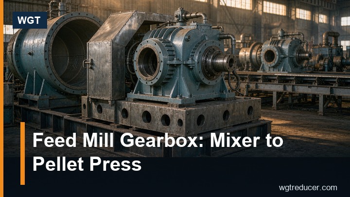
Feed Mill Gearbox: Drives From Mixer to Pellet Press | WGT
A feed mill is not one duty, it is eight duties under one roof. The mixer turns at thirty-odd revolutions per minute against a wet, sticky mass; the pellet press turns a ring die at three hundred against a die that can block in a second; the cooler creeps; the elevator runs fast. A single gearbox family can serve most of them, but the service factor and the mounting cannot be the same, and the pellet press is a case of its own. Get the station right and the plant runs; specify one service factor for the whole mill and the press will be the first thing to fail.
The Process Sets the Duty, Not the Motor
Feed arrives as grain and leaves as a pellet, and the machinery in between divides into three groups with very different torque behaviour.
- Continuous, steady loads - intake and transfer conveyors, bucket elevators, the cooler. Torque is predictable, the main enemy is dust and the occasional choke.
- Batch loads with a heavy start - mixers, molasses addition, the mash conditioner. The drive starts against a full vessel and runs light afterwards.
- Shock loads with a hard stop - the pellet press. A blocked die, a roller that stops turning, or a slug of wet mash produces a torque peak in milliseconds.
Sizing all three on one service factor is the most common specification error in a feed plant, and it is nearly always made at quotation stage.
Mixers: Low Speed, High Torque, Wet Product
A ribbon or paddle mixer runs between 25 and 45 rpm, and it starts loaded. The torque at the shaft is well above the running figure for the first few seconds, because the blades have to break the mass loose before they can move it.
| Station | Typical output speed | Torque at the shaft | Suggested service factor |
|---|---|---|---|
| Ribbon mixer, 2 m³ | 30–38 rpm | 3,500–4,500 N·m | 1.75 |
| Paddle mixer with molasses | 20–30 rpm | 5,000–8,000 N·m | 2.0 |
| Mash conditioner | 120–180 rpm | 1,200–1,800 N·m | 1.5 |
| Screw conveyor, 300 mm | 40–60 rpm | 1,200–2,000 N·m | 1.5 |
| Drag conveyor | 30–50 rpm | 2,000–3,500 N·m | 1.6 |
| Bucket elevator head shaft | 55–75 rpm | 1,800–2,600 N·m | 1.5 |
| Cooler drive | 6–12 rpm | 3,000–6,000 N·m | 1.5 |
| Pellet press main drive | 250–350 rpm | 3,000–6,000 N·m | 1.8–2.2 |
The torque column is the useful one. Torque is what sizes a case, and it comes from the duty: T (N·m) = 9550 × P (kW) ÷ n (rpm). A 15 kW motor at 35 rpm gives 4,093 N·m before any service factor; the same motor at 1,470 rpm gives 97 N·m. The motor is the same, the gearbox is not.
Mixers are also where hygiene and wash-down decisions get made. Medicated feed, poultry and ruminant lines running on the same plant need cleaning between batches, and a drive with upward-facing pockets will hold product. A smooth case, gasketed covers and a drain plug that can be reached without a spanner matter more here than an extra protection class.
Conveyors and Elevators: Dust, Choke and Holdback
Transfer equipment is where a feed mill gearbox earns its reputation quietly. The duty is unremarkable; the environment is not.
Grain dust is abrasive, it settles on every horizontal surface, and it is combustible. A drive in the elevator head house is inside the dust zone whether or not the plant has drawn the boundary on a plan. That has three consequences for the specification: a surface temperature that stays below the dust layer ignition limit, a breather that does not aspirate dust into the oil, and a finish that resists the fine dust rather than the coarse grain.
The second consequence is mechanical. An inclined conveyor stopped full restarts against its whole load, and a bucket elevator that has choked restarts against a boot full of product. The service factor has to cover that, and on an inclined run the unit also needs a backstop, because a loaded belt will run backwards the moment the motor is de-energised. A backstop is cheap at order stage and awkward to retrofit into an existing head shaft.
Alignment is the third. Elevator head shafts are long and the tower moves with load; a hollow-shaft unit removes the coupling and shortens the tolerance chain, while a foot-mounted unit with a spacer coupling is easier to shim.
Pellet Press: The Station That Decides the Mill
The pellet press is the one machine in a mill where the drive is designed around a failure mode rather than a load.
Feed mash is conditioned with steam to roughly 15–17 per cent moisture and 70–85 °C, then forced through a ring die by rollers. The die is the restriction: if the holes blind over, if the mash arrives too wet, or if a roller seizes, the torque rises until something gives. That something should be the torque limiter, not the gear teeth.
What a press drive needs:
- A service factor at the top of the range. 1.8 to 2.2 is normal for main drives, and the figure should be argued from the plant's own stop history rather than from a catalogue default.
- A torque limiter that acts before the case does. A shear pin, a slip clutch or an electronic torque limit - the choice is the plant's, but the setting must be below the gearbox's own peak rating and above the heaviest legitimate start.
- A ratio that suits the die, not the motor. Ring die speeds of 250–350 rpm from a four-pole motor land in the two-stage range, which is why press drives are usually bevel-helical rather than parallel-shaft: the motor has to sit beside the press, not behind it.
- Thermal headroom. A press house runs hot and humid and the unit often sits inside a guard, so oil temperature rather than mechanical rating can be the summer limit.
The secondary drives on a press line - feeder, conditioner, cutter - are ordinary by comparison, but they share the environment. A conditioner turning at 150 rpm with steam injected a metre away is a corrosion case as much as a torque case.
Steam, Dust and the Case That Breathes Both
A feed mill has two atmospheres that do not coexist peacefully: dry dust in the intake and grinding areas, and saturated steam around the conditioner and press.
In the dry areas the risk is dust ingress through the breather and the seal. In the wet areas it is condensation: a warm case cooling overnight draws moist air in, and the water stays in the oil. Both problems are solved at the breather, and both are made worse by a specification that only names an IP rating.
Practical measures that cost little:
- a breather taken to a clean, dry point rather than left on the case top under a dust plume;
- a membrane breather where wash-down or steam is present;
- a drain plug positioned at the true low point of the mounting orientation, not the one in the drawing;
- grease-purgeable seal gaps on the output, so dust that reaches the seal can be pushed out rather than worked in.
Sizing a Feed Mill Drive in Four Numbers
Every station on the list above can be sized from four figures: motor power, motor speed, required output speed, and the plant's service factor for that duty. Torque follows from the first and third, the ratio from the second and third, and the frame from the torque with the factor applied.
That is what the online selection system does with the same four numbers, and what a parallel-shaft unit such as the mid-range three-stage parallel shaft gear unit is built to cover on conveyor and mixer duty: three helical stages in one case, foot or flange mounting, and enough frames in the band to land on the torque rather than near it.
The step that gets skipped is the service factor. It is not a safety margin added at the end; it is a statement about how the machine is started, how often it is stopped, and what happens when the product is out of specification.
What to Send With a Feed Mill Enquiry
A quotation that comes back usable is built from six lines per station, not per plant.
- Station and duty - mixer, conveyor, elevator, cooler, press main drive, press auxiliary.
- Motor - power, speed, frame, and whether a variable frequency drive will be used.
- Output - required shaft speed, and the torque if the plant has measured it.
- Mounting - foot, flange or hollow shaft, shaft angle, and what the drive has to clear.
- Environment - dust zone, wash-down, steam, ambient range, indoor or under a roof.
- Service factor - the plant's own figure for that duty, or the incident history that justifies one.
A photograph of the mounting position is worth more than a paragraph, particularly on an elevator head where the question is always what the drive has to clear.
FAQ
Can one gearbox type cover a whole feed mill?
Most of it, yes - parallel-shaft helical units cover conveyors, mixers, coolers and elevators across the frame band. Two stations usually fall outside: the pellet press main drive, which is normally a bevel-helical unit with a torque limiter, and very slow cooler drives where a three-stage unit is needed for the ratio alone.
Why is the service factor for a pellet press so much higher?
Because the load is not proportional to the motor. A blocked die turns a normal running torque into a stall within a fraction of a second, and the drive has to survive the events that precede the limiter acting. A service factor argued from the plant's stop history is the only honest way to set it.
Does a feed mill gearbox need a backstop?
Any inclined conveyor or elevator that can run backwards when the motor stops needs one. On a loaded incline the belt will reverse as soon as power is removed, and the resulting overspeed can damage the drive, the belt and whatever is at the boot.
How does grain dust affect gearbox life?
Two ways: it blocks the breather so the case cannot equalise pressure, which pushes oil past the seals; and it enters the oil through that same path and turns into an abrasive paste. A breather piped to a clean point solves both for the price of a hose.
A feed mill rewards the plant that specifies by station: steady duty gets a conventional unit, batch duty gets a factor for the start, and the press gets a drive designed around its failure mode.
